Head Office
117, Grand Trunk Road, Salkia Howrah-700013, Kolkata, India
 Hitesh PathakWed, Feb 11, 2026
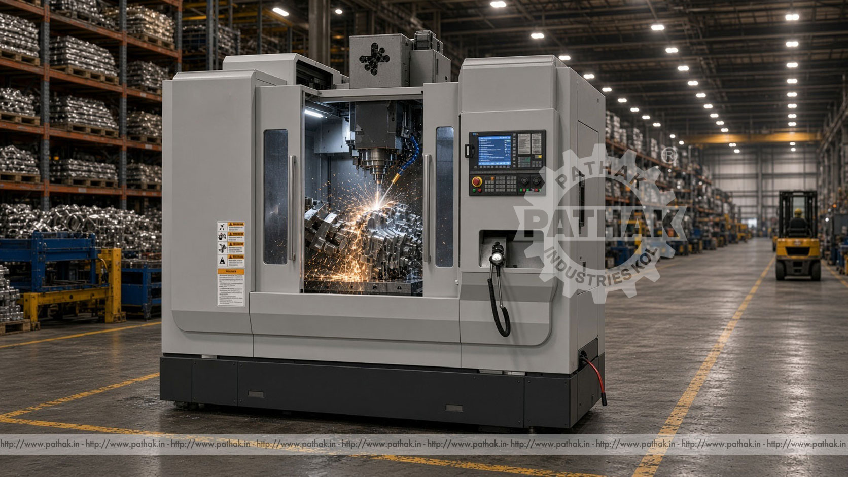
A vertical machining center brings controlled milling, drilling, boring, tapping, and related cutting operations into one CNC workstation. Its spindle is arranged vertically above the worktable, while programmed movement positions the tool and component along the machine axes. This layout makes the Vertical Machining Center useful for producing prismatic components with faces, pockets, holes, slots, profiles, and repeated features.
The Pathak Industries range contains eight TLPVMC models, beginning with the compact 600L and extending to the 1580L. Published X/Y/Z travels range from 600/400/450 mm to 1500/800/700 mm. Every listed model has a maximum spindle speed of 8000 RPM and a maximum feed speed of 10 m/min, while table size, spindle power, taper, tool capacity, loading, and rapid movement vary across the range.
A VMC is a CNC machine in which the spindle axis is vertical and the component is secured on a horizontal table. The controller interprets a program and commands coordinated movement along X, Y, and Z. X and Y generally position the table or cutting point across the work plane, while Z controls vertical approach and depth.
A tool magazine allows several cutters to be prepared for one job. The machine changes tools as the program progresses, enabling operations such as face milling, contouring, drilling, counterboring, and tapping to occur without repeatedly removing the workpiece. Actual capability depends on the selected machine, control, tooling, workholding, material, and process plan.
The process begins with a drawing or approved digital model. The programmer defines the work coordinate system, tools, spindle speeds, feeds, depths, approach moves, and cutting paths. The component is clamped in a vice, fixture, or another suitable workholding device, and each tool is measured so the controller understands its effective position.
After verification, the spindle rotates the selected cutter while the CNC axes follow the programmed path. Cutting fluid and chip evacuation help manage heat and remove material from the cutting zone. The operator inspects the first component, applies controlled offsets where necessary, and monitors tool wear during the batch.
The listed models are TLPVMC 600L, 650L, 850L, 855L, 1050L, 1160L, 1370L, and 1580L. Their names broadly reflect increasing work envelopes, but selection must use the full dimensional table. For example, 850L provides 800/500/500 mm travel and a 1000 × 500 mm table, while 855L keeps 800 mm X travel but increases Y travel to 550 mm and provides a 1000 × 550 mm table.
The 1050L offers 1000/500/500 mm travel. The larger 1160L, 1370L, and 1580L provide 1100/600/600, 1300/700/700, and 1500/800/700 mm respectively. A part must fit not only inside the travels but also within the table, enclosure, spindle-to-column clearance, and spindle-nose height after the fixture and tool are included.
Published table sizes begin at 800 × 400 mm on the 600L and 900 × 400 mm on the 650L. The 850L, 855L, and 1050L use 1000 mm-long tables with widths of 500, 550, and 500 mm respectively. Larger models increase to 1200 × 600, 1400 × 700, and 1600 × 800 mm.
Maximum table loading rises across the range: 300 kg for 600L, 400 kg for 650L, 500 kg for 850L, 600 kg for 855L, 500 kg for 1050L, 800 kg for 1160L, 1000 kg for 1370L, and 1500 kg for 1580L. This rating includes the workpiece, fixture, vice, clamps, rotary equipment, and any other load placed on the table. Distribution and permitted motion under load should also be confirmed.
The 600L through 1370L models list BT40 spindle tapers. The 1580L offers BT40/BT50, allowing the final configuration to reflect tooling size and machining demand. Taper choice affects holders, cutter capacity, rigidity, magazine compatibility, and the tooling already used in the workshop.
Spindle power begins at 5.5 kW on the 600L. The 650L lists 5.5/7.5 kW options; the 850L, 855L, and 1050L list 7.5 kW; the 1160L and 1370L list 11 kW; and the 1580L lists 11/15 kW. All published models have an 8000 RPM maximum spindle speed. Process suitability still depends on available torque, cutter diameter, material, engagement, holder, and machine configuration—not speed alone.
The 600L lists an optional 12- or 16-tool magazine, while the 650L lists 16 tools. Models from 850L through 1580L are shown with 24-tool magazines. A larger magazine allows more cutters, probes, or redundant tools to remain prepared, which can reduce interruptions during multi-operation jobs.
Magazine count should be compared with the real program rather than treated only as a higher-is-better feature. Tool diameter, neighbouring-pocket restrictions, holder mass, maximum tool length, and change sequence may affect usable capacity. Published maximum tool length is 250 mm on the 650L and 300 mm on the other listed models.
Travel values define controlled machine movement, not unrestricted component size. A fixture consumes table area, and a long cutter reduces available vertical space. The spindle-nose-to-table range begins at 100–550 mm on the 600L and extends to 190–890 mm on the 1580L, with model-specific values between them.
Distance from spindle centre to column ranges from 500 mm on the 650L to 855 mm on the 1580L. This dimension can become decisive for wide workpieces or off-centre features. A proper selection review should place the component, fixture, holder, and longest required tool within a common machine-envelope drawing.
All models list a maximum feed speed of 10 m/min. Rapid X/Y/Z rates vary: 600L is published at 30/30/25 m/min, 650L at 20/20/12 m/min, and the remaining models at 24/24/20 m/min. Rapid movement positions the axes between cutting actions; it is not the cutting feed for every operation.
Real cycle time includes tool engagement, acceleration, tool changes, probing, coolant movement, chip clearing, loading, unloading, and inspection. Programming extremely aggressive moves without considering fixture clearance can increase risk rather than useful output. Efficient machining comes from balanced toolpaths and reliable process conditions.
The component must resist cutting forces without distorting or moving. Standard vices can suit regular blocks, while dedicated fixtures may be justified for complex or repeated parts. Clamps need clear access for the spindle and should not obstruct chip evacuation. Thin or flexible parts require support that avoids bending them during clamping.
A known datum connects the drawing, program, fixture, and inspection method. Locating surfaces should be clean, and work offsets must be verified before production. For repeat work, documented fixture locations and probing routines can reduce setup variation, provided they are checked against the approved process.
Tool choice depends on material, feature, tolerance, finish, depth, accessibility, and machine interface. Face mills remove material across broad surfaces; end mills create shoulders, pockets, and profiles; drills and boring tools produce holes; and taps form internal threads. Holder length should be kept only as long as necessary because excessive overhang reduces rigidity.
Speeds and feeds should come from tool guidance and be refined for the machine, holder, engagement, coolant, and workpiece stability. Toolpaths need to manage chip load and avoid re-cutting trapped chips. Where a part requires several tools, sequence roughing, semi-finishing, finishing, and hole operations to maintain datum integrity and control distortion.
Vertical machining centers serve general engineering workshops, component manufacturers, toolrooms, maintenance departments, and production facilities. Typical parts include plates, housings, brackets, flanges, blocks, dies, fixtures, manifolds, machine elements, and prepared castings or forgings whose geometry fits the selected work envelope.
The vertical layout provides convenient visibility and top access for many prismatic components. It is well suited to parts with most features accessible from one primary orientation. Components requiring extensive machining on many sides may need multiple setups or compatible rotary equipment, which should be considered when estimating accuracy and cycle time.
Programs should be checked for coordinate errors, incorrect tool calls, unsafe approach positions, and excessive travel. Simulation or graphical verification is useful, but it cannot confirm the exact physical position of every clamp and fixture. Operators should verify tooling and offsets at the machine and prove a new cycle under controlled conditions.
The first part needs inspection against the drawing. Adjustments should be entered through authorised wear or work offsets rather than undocumented program changes. Once approved, the program revision, setup sheet, tool list, fixture details, and inspection result should be retained for repeat orders.
The product table publishes model-specific positioning and repositioning values. These machine figures are not an automatic guarantee for every finished component. Part accuracy also depends on thermal condition, calibration, fixture stability, tool runout and wear, cutting force, material movement, programming, and measurement practice.
Users with critical tolerance requirements should agree on an acceptance method and relevant standards for the selected model. Routine checks using known artefacts can reveal drift before it appears across a large batch. Environmental control and a consistent warm-up routine may also matter in precision work.
Published machine dimensions range from 1900 × 1700 × 2240 mm for the 600L to 3800 × 2720 × 3610 mm for the 1580L. Machine weights range from 3500 to 13,000 kg. These values affect freight, doorway clearance, lifting capacity, floor loading, foundation preparation, and final positioning.
Allow additional space for chip removal, coolant service, electrical cabinets, tool loading, doors, maintenance, and safe operator access. Installation planning should also confirm power, earthing, compressed air where required, coolant handling, extraction needs, and ambient conditions.
The enclosure and interlocks protect users from rotating tools, flying chips, coolant, and automatic movement. They must not be bypassed. Workpieces, fixtures, and tools should be secured before the spindle starts, and doors should remain closed during automatic machining. Chip removal requires suitable tools rather than bare hands.
Daily care includes checking lubrication, coolant level and condition, tool retention, air supply where applicable, guards, alarms, and visible leaks. Chips should be cleared from areas where they can obstruct movement or seating. Scheduled work includes spindle, guideway, tool changer, coolant, electrical, and geometric checks according to the manual. Maintenance requires energy isolation and qualified personnel.
Begin with representative components. Record overall size, material, mass, features, tolerances, surface finish, batch quantity, and the number of setups. Add fixture dimensions and weight, then calculate the reach and clearance of the longest tools. This creates a realistic work envelope.
Compare travel, table size and load, spindle taper and power, spindle speed, tool magazine, clearances, rapid rates, controller needs, installation space, and future parts. Pathak Industries can review component drawings against the eight-model range, but the chosen configuration and performance acceptance should be documented before purchase.
Depending on tooling and configuration, it can perform milling, drilling, boring, tapping, profiling, pocketing, and related CNC cutting operations on suitable components.
The listed models extend from 600/400/450 mm to 1500/800/700 mm X/Y/Z travel, with six intermediate work envelopes.
Models through 1370L list BT40. The 1580L lists BT40/BT50, with the final taper to be confirmed for the ordered configuration.
All eight models show a published maximum of 8000 RPM. Suitable operating speed depends on the cutter, material, holder, and cutting conditions.
The range lists 12/16 optional positions on 600L, 16 on 650L, and 24 on models from 850L through 1580L.
No. Finished accuracy also depends on setup, tooling, thermal state, material, cutting forces, calibration, programming, and inspection.
Include the combined weight of the workpiece, fixture, vice, clamps, rotary equipment, and every item carried by the table.
Provide component drawings, materials, sizes, weights, tolerances, batch quantities, operations, tooling preferences, controller needs, utilities, and installation constraints.
The best vertical machining center is not necessarily the largest model. It is the machine whose travels, table, clearances, spindle, tooling, controller, and load capacity accommodate the planned components with a sensible margin. Process engineering, secure workholding, verified programs, tool management, and maintenance then turn that hardware into dependable production.
Review the complete comparison table on the Vertical Machining Center product page and share representative components with Pathak Industries. Confirm the model, spindle option, CNC system, magazine, accessories, installation details, and acceptance requirements in the final technical offer.