Head Office
117, Grand Trunk Road, Salkia Howrah-700013, Kolkata, India
 Hitesh PathakTue, Aug 18, 2026
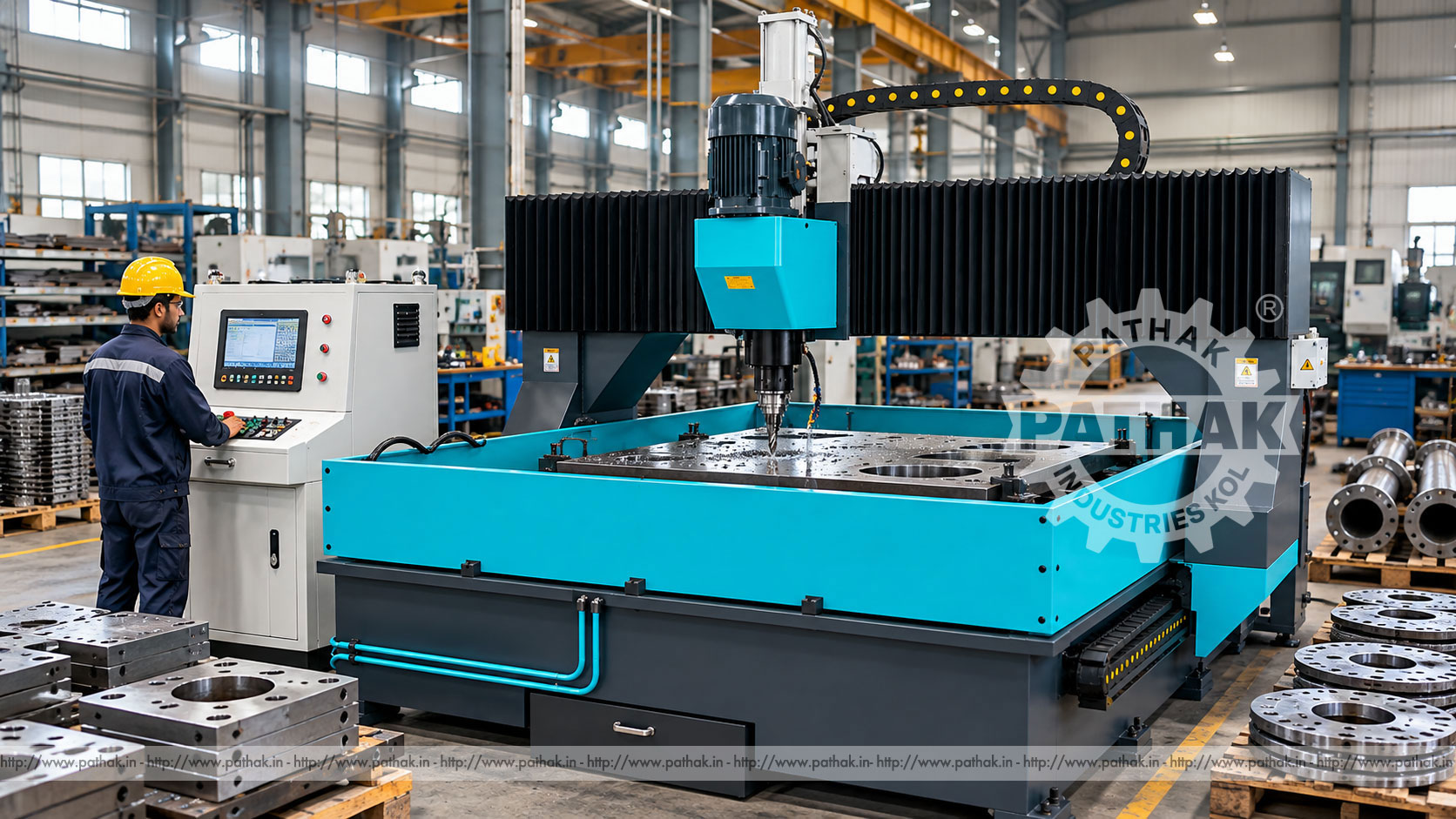
Large plates and fabricated components often contain repeated hole patterns that must align with mating structures, fasteners, flanges, or assembled equipment. Marking and drilling every location manually can consume significant time and introduce cumulative positioning error. A Gantry Type CNC Drilling Machine combines a fixed work-support area, travelling gantry, programmable positioning, and hydraulic drilling heads to create organised hole patterns in suitable metal work.
The Pathak Industries range includes TLP-PD-2016, TLP-PD-2016/2, TLP-PD-3016, and TLP-PD-3016/2. The 2016 models provide a 2000 × 1600 mm processing scope, while the 3016 versions extend the first dimension to 3000 mm. The “/2” versions use two spindles instead of one. All four list 100 mm stack thickness, a Morse No. 4 taper, 120–560 RPM spindle speed, 180 mm feed stroke, hydraulic clamping, and PLC plus industrial-computer control.
A gantry drilling machine carries one or more drilling heads on a bridge-like structure spanning the work area. CNC axes position the head over programmed coordinates while the plate or component remains clamped on the table. The spindle then feeds axially into the material to create the specified hole.
This arrangement is useful for wide plates because the gantry can reach positions across the work without repeatedly marking, unclamping, and moving the component by hand. Its value increases when many holes share a common datum or when the same pattern returns across a production batch.
The process begins with an approved drawing or coordinate file. Hole locations, diameters, depths, and tool requirements are entered or imported into the control workflow. The operator loads the plate or stack, aligns it to the machine reference, and activates the hydraulic clamps after confirming that all contact points are clear.
The gantry and drilling head move to the first coordinate. The spindle rotates at a selected speed within the supported range, and the hydraulic automatic-stroke head feeds the tool through the work. After retracting, the machine moves to the next location. The component remains referenced until the programmed pattern is complete.
TLP-PD-2016 and TLP-PD-2016/2 have a published processing scope of 2000 × 1600 mm. TLP-PD-3016 and TLP-PD-3016/2 provide 3000 × 1600 mm. The longer models suit components that require hole patterns spread across a greater first-axis length.
Processing scope is not the same as unrestricted overall workpiece size. Clamps, supports, datum stops, tool clearance, and access may reduce usable conditions for a particular part. A representative drawing should be overlaid on the working envelope before selecting the model.
The standard 2016 and 3016 models list one spindle. Their /2 counterparts list two. A twin-spindle machine can support paired or parallel drilling strategies where the component pattern and spacing make effective use of both heads. It should not be assumed to complete every program in exactly half the time.
Productivity depends on hole distribution, tool requirements, head spacing and movement, loading, clamping, drilling conditions, and whether both spindles can operate efficiently on the same job. Parts dominated by irregular coordinates may not benefit in the same way as repetitive plate patterns.
All four models list a stack thickness of 100 mm. Stack drilling can process several compatible plates in one setup, but the layers must be flat, clean, aligned, and clamped so they cannot move or separate during penetration. Trapped scale, burrs, or uneven plates can disturb the stack and hole location.
The total material condition, tool reach, chip evacuation, and breakthrough behaviour must suit the proposed stack. Published stack thickness should not be interpreted as a universal drilling depth for every material or hole diameter. Confirm the actual combination during process planning.
The spindle specification is a Morse No. 4 taper hole across the range. Tool shanks, sleeves, adaptors, and holders must match this interface and remain in sound condition. Clean taper contact is important because chips or damage can cause runout, poor retention, and inaccurate holes.
Drill selection depends on material, hole diameter, depth, stack, spindle power, and coolant or lubrication method. Suitable tooling may include compatible twist drills or other approved hole-making tools. The product’s imported diameter row is unclear, so the required hole range should be confirmed explicitly in the final technical offer.
Published spindle speed is 120–560 r/min. The selected speed should follow the tool diameter, cutting material, workpiece grade, and tool provider’s guidance. Large drilling tools generally operate differently from smaller tools, while harder materials may require revised conditions.
The hydraulic automatic-stroke drilling head has a listed feed stroke of 180 mm. Stroke describes available head movement, but usable drilling depth also depends on tool length, holder, clearance, work stack, breakthrough allowance, and machine setup. Feed should produce controlled chips without overloading the tool or spindle.
Single-spindle TLP-PD-2016 and TLP-PD-3016 models list 5.5 or optional 7.5 kW main motor configurations. Twin-spindle models list 5.5 × 2 or optional 7.5 × 2 kW. The selected power should reflect the approved drilling range, material, production duty, and tooling.
More motor power does not replace correct speed, feed, tool geometry, and clamping. Electrical planning should confirm the chosen configuration, total connected load, protective devices, earthing, cable routes, and supply stability before installation.
The product table lists twelve clamping cylinders with 7.5 kN clamping force and double-side button control on the gantry. Distributed clamping helps hold plate or stacked work against the machine support during positioning and drilling.
Clamping faces and supporting surfaces must be clean. Scale or chips underneath a plate can tilt it and alter hole location. Controls should require the authorised procedure so workers cannot place hands near a clamp while another person activates it from the opposite side.
The listed hydraulic-pump pressure is 6 MPa. Hydraulics support the automatic-stroke drilling heads and clamping functions in the supplied arrangement. Correct oil, filtration, temperature, pressure, and leak-free connections are important for repeatable movement.
Operators should not raise pressure to compensate for dull tools, poor setup, or mechanical obstruction. Unstable feed should be diagnosed by checking tooling, material, hydraulic condition, and programmed parameters. High-pressure leakage requires safe isolation and qualified repair.
The control system is specified as PLC+IPC. The industrial computer supports job data and coordinate control, while the PLC manages machine sequence, input/output logic, clamping, and related functions. This combination supports repeatable execution of approved patterns.
Program revisions should be controlled so the operator can confirm that the loaded plate matches the active file. Coordinate systems, plate orientation, and datum positions must be verified before starting. A program that is geometrically correct can still drill the wrong face or mirrored pattern if setup orientation is incorrect.
Hole data should originate from the approved drawing. The programmer needs coordinates, diameters, through or blind status, tolerances, and any sequence requirements. Repeated patterns can be organised to reduce unnecessary gantry movement while maintaining safe tool and clamp clearance.
Where twin heads are used, the program should distribute work in a manner consistent with their permitted movement and spacing. Simulation and dry checks can identify coordinate errors, but the first workpiece still requires controlled proving and inspection.
Gantry CNC drilling machines can serve steel-fabrication shops, equipment manufacturers, structural component producers, engineering facilities, and plate-processing departments. Typical work includes base plates, flanges, tube sheets, structural connection plates, machine frames, large brackets, and fabricated assemblies that fit the processing envelope.
The machine may prepare components for bolting, assembly, welding fixtures, or later machining. It can also support repeat hole patterns across batches where coordinate control reduces manual layout effort. Material and hole requirements must remain within the confirmed tool and machine capability.
The product data lists drilling precision of ±0.5 mm and repositioning precision of ±0.2 mm. These are published machine values, not automatic guarantees for every finished part. Actual hole position also depends on datum accuracy, plate movement, tool runout and deflection, stack condition, thermal effects, and measurement practice.
The first piece should be inspected against the drawing using an appropriate method. Hole diameter, position, perpendicularity, burr, and surface condition may all matter. If a stack is drilled, inspect whether layers shifted and whether the lower plates meet the same requirements as the top.
Drilling creates chips within a confined hole. Their shape and evacuation reveal whether cutting conditions are effective. Packed chips can damage the tool, mark the hole, or increase load. Deep or stacked work may require a strategy that clears chips safely without compromising the cycle.
Tool life depends on speed, feed, material, cooling or lubrication, runout, rigidity, coating, and chip evacuation. Recording holes completed per tool can help identify gradual changes. A worn drill should be replaced or serviced before it begins producing oversize, tapered, rough, or misplaced holes.
The stored specification lists overall size as 3500 × 2650 × 2870 mm for the range. Final installation drawings should be checked for the selected single- or twin-head configuration. Additional space is needed for material loading, operator access, electrical and hydraulic service, chip removal, and maintenance.
The floor or foundation must support the machine and workpiece loads while maintaining level and alignment. Plan lifting and transport access before delivery. Utilities, lighting, coolant or lubricant handling, and chip disposal should be ready for commissioning.
Rotating tools, moving gantries, hydraulic clamps, chips, and heavy plates create entanglement, crushing, cutting, and trapping hazards. Guards, barriers, interlocks, and emergency stops must remain functional. Workers should stay outside gantry travel and clamp zones during automatic operation.
Heavy workpieces require suitable lifting devices and approved attachment points. Chips should be removed with tools after the machine reaches a safe condition. Before changing tooling, clearing a jam, entering a restricted area, or servicing the machine, isolate electrical and hydraulic energy and release stored pressure.
Daily checks should cover tooling, spindle taper, clamps, supports, hydraulic pressure and leaks, lubrication, guards, sensors, controls, cable carriers, and chip accumulation. Keep datum and support surfaces clean so the next plate seats correctly.
Scheduled service includes spindle and feed-head inspection, hydraulic oil and filters, clamping cylinders, axis drives, guide systems, electrical cabinets, control backups, and geometric verification. Maintenance records support diagnosis of repeated accuracy or feed problems.
Start with representative plate drawings. Record maximum length, width, thickness or stack, material grade, hole diameters, depth, quantity, spacing, tolerance, and batch size. Decide whether the hole patterns can make productive use of one or two spindles.
Compare processing scope, spindle count, motor option, tooling interface, feed stroke, clamping, control workflow, installation space, and utilities. Pathak Industries can assess drawings against the four TLP-PD models. The exact drilling-diameter range and process acceptance should be confirmed before ordering.
It creates programmed hole patterns in suitable plates, stacks, castings, and fabricated components while the work remains clamped on a fixed support area.
The 2016 models list 2000 × 1600 mm, while the 3016 models list 3000 × 1600 mm processing scopes.
Standard TLP-PD-2016 and 3016 models list one spindle; the corresponding /2 models list two spindles.
All four configurations list 100 mm. Actual suitability depends on material, hole, tooling, clamping, and chip evacuation.
The range lists a Morse No. 4 taper and spindle speeds from 120 to 560 r/min.
The imported source row is unclear, so the required standard and optional diameter range should be confirmed in writing for the final configuration.
Not for every job. Benefit depends on pattern layout, head movement, tool sizes, drilling conditions, loading, and how effectively both spindles can share the work.
Provide drawings, plate sizes, stack thickness, materials, hole diameters and depths, tolerances, batch quantities, utilities, loading method, and preferred spindle count.
A gantry CNC drilling machine improves plate processing when work envelope, spindle count, tooling, clamping, programs, and inspection are planned together. The longer or twin-spindle model is valuable only when the actual components use its additional reach or parallel capability.
Review all four options on the Gantry Type CNC Drilling Machine product page and share representative drawings with Pathak Industries. Confirm drilling range, motor option, tooling, control workflow, utilities, installation, and acceptance criteria in the final technical offer.