Head Office
117, Grand Trunk Road, Salkia Howrah-700013, Kolkata, India
 Hitesh PathakMon, Sep 14, 2026
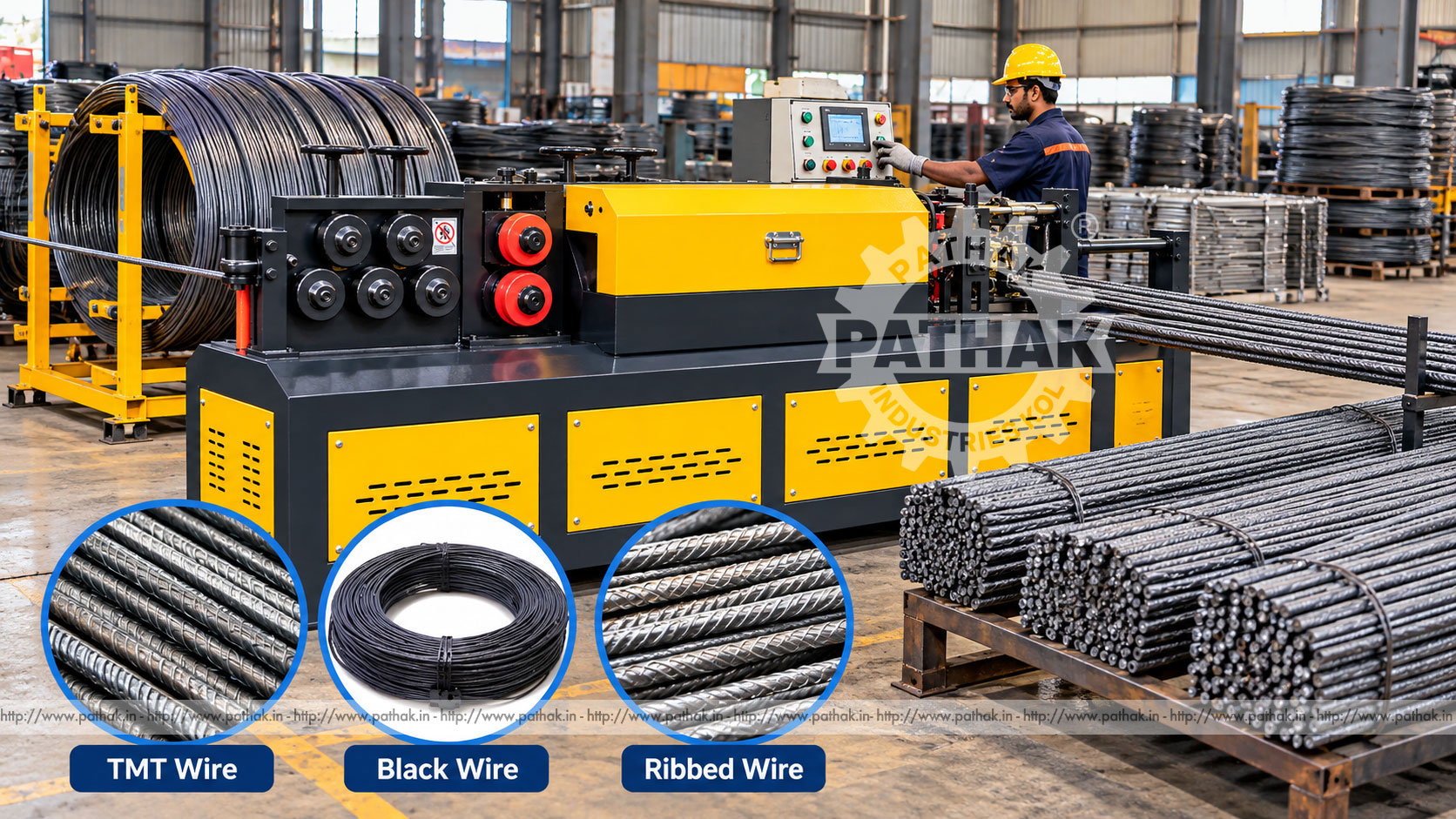
Coiled TMT and ribbed wire is economical to transport and store, but many downstream operations require straight pieces cut to repeat lengths. Manually pulling, straightening, measuring, and cutting heavy ribbed material is slow, physically demanding, and difficult to standardise. An Automatic TMT or Ribbed Wire Straightening and Cutting Machine combines these operations into a coordinated production process.
Pathak Industries lists two models for this work. The PWWS TMT-010 covers 6 to 10 mm material with a published feeding capacity of 70 metres per minute, while the PWS TMT-014 covers 8 to 13 mm material with feeding up to 90 metres per minute. Both models list semi-automatic cutting at selected lengths and automatic production at 20- and 40-foot lengths. This guide explains how the process works, how the models differ, and what affects straightness, length accuracy, output, safety, and machine selection.
This machine converts coiled TMT, ribbed wire, or other approved reinforced-profile material into straight, measured pieces. A powered feed draws the material from a suitable payoff, the straightening section removes coil curvature, a measuring arrangement determines the required length, and the cutting unit separates the finished piece.
The process is designed for repeated production. It reduces individual manual measurements and keeps feed, straightening, and cutting within one controlled workflow. The result still depends on correct material, setup, straightening adjustment, cutter condition, collection support, and operator supervision.
Material begins on a controlled coil payoff designed for its weight and stored energy. Guides lead the wire into the feed and straightening arrangement. Powered rolls pull the wire through a sequence of straightening elements that apply controlled corrective bends to counter the curvature created during coiling.
The straightened material advances through the length-measuring section. When the selected length is reached, the feed pauses or coordinates with the cutting mechanism, and the bar is sheared. The completed piece moves onto a receiving bed or collection system, after which the next cycle begins.
Long products require support throughout discharge. If a 20- or 40-foot piece is allowed to sag, strike the floor, or push against an obstruction, it can affect straightness, interfere with length control, damage the surface, or create a serious handling hazard.
The PWWS TMT-010 is listed for material from 6 to 10 mm. Its published feeding capacity is 70 metres per minute. The stated motor arrangement is 2 + 10 HP at 1440 rpm. Listed net and gross weights are approximately 1100/1300 kg for the semi-automatic version and 2200/2550 kg for the automatic version.
The PWS TMT-014 covers the heavier 8 to 13 mm range and has a published feeding capacity of 90 metres per minute. Its listed motor arrangement is 2 + 15 HP at 1440 rpm. Approximate net and gross weights are 1500/1800 kg for the semi-automatic version and 2600/3000 kg for the automatic version.
The larger model should not be selected on speed alone. Buyers should base the choice on actual rib profile, diameter range, strength, coil condition, required straightness, cut length, production mix, collection system, and available utilities.
Both models list semi-automatic operation for selected lengths and automatic production at 20 and 40 feet. Those long standard lengths suit many reinforcement and fabrication workflows, but buyers should confirm the exact measuring system, programmed options, tolerance, and receiving arrangement required for their plant.
A cut-length specification should include nominal length, permitted variation, measurement temperature where relevant, end condition, burr allowance, batch quantity, and identification method. The collection bed must accommodate the full product without uncontrolled overhang.
Length verification should use a calibrated method. Checking only the first piece is insufficient because feed-roll slip, wear, scale, rib geometry, or changing coil tension can introduce drift during a batch.
TMT material has a deformed surface intended to improve mechanical bond in reinforced applications. Those ribs alter how the wire contacts feed rolls, guides, straightening elements, and cutters. Two products with the same nominal diameter may behave differently because of rib height, pattern, strength, ductility, coil cast, and surface scale.
Before production, confirm nominal and actual diameter, rib geometry, material grade, tensile and yield properties, elongation, coil weight, inside and outside coil dimensions, and surface condition. Representative coil samples are valuable when selecting rolls, guides, cutters, and machine settings.
Heavily rusted, damaged, tangled, or irregular coils should not be introduced without review. Poor material can increase wear, reduce traction, disturb measurement, and create unsafe payoff behaviour.
Straightening is a controlled balancing process. Insufficient correction leaves residual bow or coil set. Excessive correction can mark the ribs, work the material unnecessarily, accelerate tool wear, or create curvature in the opposite direction.
Adjustment should begin conservatively and proceed using measured trial pieces. Operators should check straightness over the specified reference length and in more than one plane. Long pieces need level support during inspection so their own weight does not create a misleading result.
When changing diameter, grade, rib pattern, or supplier, the previous settings may no longer be suitable. Record approved adjustments for each validated product, but always verify the first pieces from a new coil or batch.
The cutting system must separate ribbed material cleanly at the required rate. Cutter material, geometry, clearance, alignment, and condition influence cutting load, end deformation, burrs, noise, and tool life. Larger or stronger material generally demands more from the cutting unit.
Inspect cut ends for excessive flattening, cracking, sharp projections, and inconsistency. A gradual reduction in cut quality may indicate tool wear or alignment change. Tool servicing should be planned from condition and recorded production rather than delayed until failure.
The listed feed rates of 70 and 90 metres per minute are useful machine reference values, not automatic guarantees of saleable shift output. Finished pieces per minute depend heavily on cut length. Long 40-foot bars require fewer cutting cycles per metre than short components, while coil changes and finished-bundle removal reduce effective operating time.
Production records should distinguish metres fed, pieces cut, accepted pieces, scrap, downtime, coil changes, setup time, and tool changes. This reveals whether the principal constraint is feeding, cutting, payoff, collection, bundling, inspection, or material quality.
A balanced line must handle the output after cutting. If straight bars cannot be cleared, counted, and bundled safely, increasing feed speed only shifts the bottleneck downstream.
Straightened and cut TMT or ribbed wire can support:
Material used for structural or regulated work must retain the required traceability and comply with the applicable grade, standard, and fabrication procedure. Straightening and cutting should not be assumed to certify the finished material.
Feeding, straightening, measuring, and cutting occur in one arranged workflow, reducing repeated movement between separate workstations.
A validated measuring setup supports batch production at defined lengths, with routine inspection used to identify drift.
Powered feeding limits the need to pull heavy wire through the machine manually. Safe coil loading and finished-bar handling equipment remain essential.
Standard lengths can be produced, counted, identified, and bundled according to planned orders and downstream operations.
Coiled TMT stores substantial energy. The payoff must be rated for the coil mass and dimensions, control unwinding, and keep personnel away from expanding loops. Coil restraints should only be removed through the approved loading procedure.
The path between payoff and machine should avoid sharp changes in direction, uncontrolled contact, and pedestrian traffic. Changing payoff drag can affect feeding and measurement, so smooth controlled delivery is important for process stability.
Twenty- and forty-foot pieces require long, aligned support. The receiving arrangement should prevent sagging, uncontrolled fall, rebound, or collision with personnel and equipment. Guides or stops must suit the full diameter range and should not damage the ribs.
Finished pieces may require automatic or manual counting, transfer, strapping, tagging, and lifting. Bundle size should match downstream handling equipment and safe working limits. The layout must keep lifting paths clear of the operating position.
Installation planning should consider the machine, payoff, full infeed path, longest discharge length, receiving bed, bundle area, operator access, maintenance zones, control station, and material-handling routes. The automatic versions' listed weight is significantly higher than that of the semi-automatic units, so foundation and lifting plans must match the selected configuration.
Electrical supply, protection, earthing, voltage, phase, and frequency should be confirmed for the stated motor arrangement. Qualified commissioning personnel should verify alignment, rotation, guards, emergency controls, lubrication, measuring equipment, cutters, feed direction, and all supporting equipment.
Routine inspection should cover input diameter and profile, finished length, straightness, cut-end condition, surface or rib damage, piece count, bundle identification, and material traceability. Check after startup, coil changes, adjustments, cutter service, and at planned production intervals.
Length drift may result from feed slip, measuring-wheel wear, rib or scale buildup, changing coil tension, or incorrect calibration. Curvature can indicate unsuitable straightening adjustment, worn components, guide misalignment, or changing material properties. Surface scoring requires inspection of every contact point.
The line includes heavy coils, stored wire energy, powerful feed rolls, straightening mechanisms, cutters, moving bars, and long discharge zones. Only trained personnel should operate, adjust, or maintain it. Guards, barriers, interlocks, and emergency controls must remain functional and correctly positioned.
No person should enter the coil expansion zone, feed area, cutter, or discharge path while hazardous movement is possible. Jams, tool changes, and maintenance require isolation and verification of all relevant energy. Finished bars can move unexpectedly and should be handled using the defined collection and lifting procedure.
Personal protective equipment should be selected through the site's risk assessment. It supports, but does not replace, guarding, controlled access, mechanical handling, and energy isolation.
Daily checks should include guides, feed rolls, straightening parts, cutters, drives, guards, sensors, cables, lubrication points, payoff equipment, and the receiving bed. Remove scale and fragments safely because buildup can affect traction, measurement, and alignment.
Monitor cutter condition, roll wear, bearing temperature, fastener security, unusual noise, vibration, and changes in finished quality. Record tool life and adjustments by material diameter and grade.
Periodic maintenance should include alignment and calibration checks, drive service, electrical enclosure cleaning, safety-device testing, lubrication-system review, and examination of foundations and anchors. Maintenance records allow planned intervention before defects or downtime increase.
Choose between the PWWS TMT-010 and PWS TMT-014 from actual material and output needs. Provide the minimum and maximum diameters, rib geometry, material grade and tensile range, coil size and weight, required straightness, cut lengths, length tolerance, daily volume, bundle size, electrical supply, and available space.
Also confirm whether semi-automatic or automatic length production is required, how 20- or 40-foot pieces will be supported, and what payoff, counting, bundling, lifting, and guarding equipment is included. Pathak Industries can review representative material and production details against the available models.
The published range is 6 to 10 mm. Actual suitability also depends on rib geometry, material properties, coil condition, and the approved tooling.
The listed range is 8 to 13 mm, making it the heavier-capacity option of the two stated models.
The PWWS TMT-010 is listed at 70 metres per minute and the PWS TMT-014 at 90 metres per minute. Net output depends on cut length and the complete production workflow.
Yes. Both specifications list automatic production at 20 and 40 feet, along with semi-automatic work at selected lengths. Confirm the exact measuring and receiving arrangement.
It supports the straightened piece, protects accuracy and surface condition, and prevents long bars from falling or moving unpredictably after cutting.
Possible causes include feed slip, measuring-system wear or contamination, changing coil drag, incorrect calibration, or unstable material contact.
No. Diameter, rib profile, strength, coil cast, and supplier variation can change straightening and feeding behaviour. Verify the first pieces after each relevant change.
Provide material grade, diameter range, rib profile, coil dimensions and mass, cut lengths, tolerance, straightness requirement, daily output, bundle plan, power supply, and representative samples where possible.
The Pathak Industries PWWS TMT-010 and PWS TMT-014 provide integrated feeding, straightening, measuring, and cutting for coiled TMT or ribbed material. Their combined 6 to 13 mm listed range, 70- and 90-metre-per-minute feed capacities, and semi-automatic or standard 20- and 40-foot production options support a variety of reinforcement and wire-processing workflows.
Successful production depends on choosing the correct model, controlling the coil safely, supporting long output, validating straightening settings, monitoring length and cut quality, and maintaining the feed and tooling systems. Clear material data and finished-piece requirements are essential for selecting and configuring the line correctly.