Head Office
117, Grand Trunk Road, Salkia Howrah-700013, Kolkata, India
 Hitesh PathakWed, Sep 30, 2026
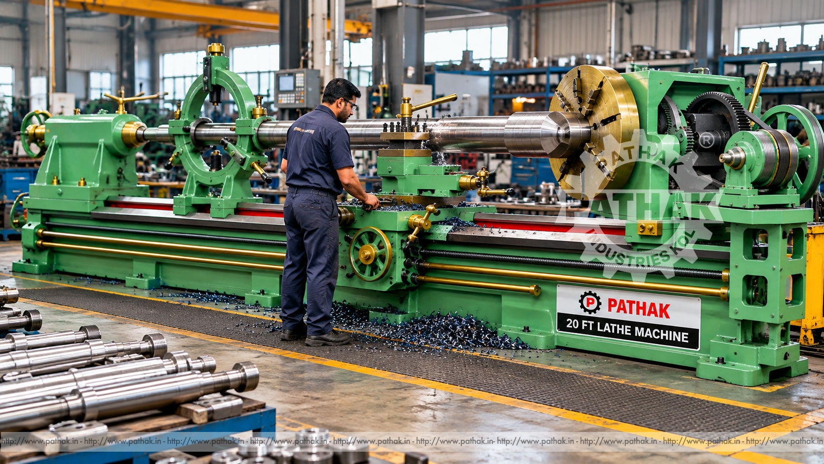
Long shafts, rolls, tubes, sleeves, and repair components require more than a standard workshop lathe. The bed, spindle, carriage, tailstock, workholding, and supporting equipment must remain stable across a much larger working envelope. A 20 FT Lathe Machine provides the extended structure and heavy-duty arrangement required for suitable long rotational parts.
The Pathak Industries HL-20 is the largest model in a published series ranging from HL-4 to HL-20. The HL-20 lists a 20-foot bed, 22-inch bed width, 20-inch centre height above the bed, 30-inch swing over the saddle, 60-inch swing in the gap, 11-foot admission between centres, a 4-1/8-inch hollow spindle, six spindle speeds, 7.5 HP power, and an approximate net weight of 5200 kg. This guide explains how to interpret those capacities and plan safe, accurate long-work machining.
A 20-foot lathe is a long-bed conventional turning machine intended for components whose setup and support exceed the practical range of smaller lathes. The work rotates in a chuck, faceplate, or between centres while a cutting tool travels along the bed to generate cylindrical, faced, stepped, bored, grooved, tapered, or threaded features.
The “20 FT” designation in this product range refers to the listed bed length. It should not be interpreted as 20 feet between centres. For HL-20, the published admission between centres is 11 feet. Actual usable component length depends on the chuck, centres, tailstock, steady rests, tooling, and required approach clearance.
The stored HL-20 data lists:
These figures define key machine dimensions, but a proposed job must still be checked as a complete setup. Workholding diameter, jaw position, carriage clearance, steady-rest location, tailstock length, tool approach, and lifting access can all reduce usable capacity.
Bed length describes the main structural way length, not the exact longest workpiece. Headstock, gap, carriage, tailstock, and end clearances occupy part of the overall bed. The HL-20 therefore lists 11 feet between centres despite its 20-foot bed.
A part held partly inside a hollow spindle, mounted on a faceplate, or supported in another approved arrangement may use the machine envelope differently. Buyers should provide drawings showing total length, machined length, chucking allowances, centre holes, and all maximum diameters.
Swing over the saddle identifies the largest theoretical diameter that can rotate above the carriage area. The HL-20 lists a 30-inch diameter. Practical capacity depends on tool holder, cross slide, jaws, irregular features, and safe clearance throughout rotation.
The gap permits larger-diameter short sections near the headstock and is listed at 60 inches diameter for HL-20. This does not mean a 60-inch diameter can be machined along the full bed. Gap work is limited by gap width, workholding, carriage and tool access, balance, machine speed, and component geometry.
The published 4-1/8-inch hollow spindle can accept suitable stock through the spindle bore. Through-spindle work can simplify machining of bars, tubes, and pipe ends, but stock diameter, straightness, rear projection, support, guarding, and spindle hardware must all be considered.
Unsupported bar projecting from the rear of a spindle can whip violently. Long material must be contained and supported by equipment designed for the speed, diameter, and mass. The entire rotating length should be included in the safety review.
The HL series lists six spindle speeds. Speed selection must suit work diameter, material, balance, tool, operation, and workholding. Large components require much lower rotational speed than small shafts because surface speed rises with diameter.
Heavy, irregular, welded, or partially machined parts should begin at a conservative speed after balance and mounting checks. The chuck, faceplate, centres, and any steady-rest contact must be rated for the selected conditions. Never select speed solely from the motor rpm.
A long shaft can bend under its own weight and deflect under cutting force. Tailstock support controls one end, while fixed or travelling steady rests may support intermediate sections. Support locations should be planned so the carriage and tool can reach all required features without collision.
Steady-rest pads or rollers must be aligned, lubricated where applicable, and adjusted evenly. Too much pressure can distort the component or generate heat; too little support permits vibration. The contact diameter should be round and suitably finished before the steady carries the cutting load.
Slender work may need staged machining, follower support, reduced depth, suitable tool geometry, and careful sequencing to control deflection.
Long and heavy parts may be mounted between centres, in a chuck with tailstock support, on a faceplate, or using a job-specific fixture. The selected method must transmit torque, locate the part, resist cutting force, and permit safe speed without slippage.
Chuck jaws should engage adequately and remain within approved limits. Irregular work requires careful balancing, often at low speed. Faceplate clamps and counterweights must be positively secured. Centre holes should be correctly formed and maintained for between-centres work.
Because the component may exceed manual handling limits, lifting plans should identify approved sling points, crane capacity, centre of gravity, tag-line use, and the people responsible for placement.
An appropriately configured HL-20 can support:
Final suitability depends on the part material, dimensions, tolerance, finish, workholding, tooling, support, and required output.
Long-bed lathes are used in general engineering, heavy repair shops, rolling and process industries, agricultural equipment service, transport maintenance, shaft manufacturing, pump and valve repair, paper and textile machinery support, and fabrication plants.
Representative components include transmission shafts, line shafts, rollers, drums, tubes, sleeves, pump shafts, mill parts, heavy pins, and replacement components for legacy machinery. Regulated or critical parts require approved procedures, material traceability, inspection, and engineering acceptance.
At approximately 5200 kg net weight, the HL-20 requires a foundation and lifting plan based on the actual machine drawing and site conditions. The floor must support the static load, workpiece, tooling, operators, and dynamic cutting forces.
Long beds require careful levelling along their full length. Foundation settlement, uneven support, or thermal gradients can affect alignment. Installation should include precision levelling, anchor control, and verification after an initial settling period.
Provide clearance for loading long parts, moving the tailstock and steadies, full carriage travel, chip removal, electrical isolation, belt or gear service, and operator access. Overhead crane coverage or another rated handling system is often essential.
Tool material and geometry should suit the component material, scale, interrupted sections, rigidity, and required finish. Heavy roughing tools need a strong holder and short projection. Finishing tools require a controlled nose radius, stable support, and appropriate feed.
Cutting data should reflect actual diameter because surface speed varies across stepped or tapered work. As diameter changes, the selected rpm may need review. Depth and feed must remain within the machine, tool, workholding, and support capacity.
Coolant or cutting fluid, where appropriate, should reach the cutting edge without creating slip, visibility, or housekeeping problems. Chips from long turning operations can be large and continuous, requiring controlled chip-breaking and safe removal.
Deflection can produce unwanted taper, chatter, or dimensional variation. Reduce unsupported length, position steadies effectively, maintain sharp tools, control cutting force, and use balanced stock-removal sequences.
If a diameter changes along the shaft, check work deflection, tailstock alignment, bed level, tool wear, support pressure, and thermal condition. Measurements should be taken at defined stations with calibrated instruments and a consistent technique.
Inspection may include overall length, diameter at several positions, roundness, runout, straightness, shoulder location, bore size, thread pitch and form, surface finish, and concentricity between features. The method should match the drawing and functional requirements.
Large parts may require in-process measurement because removal and remounting can change alignment. Allow for temperature stabilisation and remove chips or oil from measuring surfaces. Record readings so trends can be corrected before the final pass.
A long-bed lathe can rotate heavy components with considerable stored energy. Exclusion zones, guards, barriers, and operating procedures must reflect the complete rotating envelope, including chuck jaws, clamps, counterweights, rear-projecting stock, and irregular features.
Never stand in line with an unproven faceplate or irregular setup during initial rotation. Keep hands, clothing, gloves, rags, measuring tools, and jewellery away from rotating components. Stop the spindle before measurement, chip removal, or adjustment near the work.
Use a chip hook or brush rather than hands. Isolate and verify energy before changing chucks, adjusting belts or gears, servicing the machine, or entering guarded areas. Lifting and tailstock movement should follow approved procedures.
Daily checks should include lubrication, bed and slide cleanliness, chuck and jaw condition, tool clamping, tailstock and steady locks, guards, controls, drive condition, and foundation surroundings. Remove chips without damaging guideways.
Monitor spindle and bearing sound, temperature, gear behaviour, feed and leadscrew condition, backlash, carriage movement, coolant, and electrical equipment. A long machine should be checked periodically for level and alignment, particularly after installation or foundation work.
Maintenance records should capture lubrication, adjustments, repairs, alignment readings, tool incidents, and accuracy checks. Planned service reduces the risk of discovering wear during a critical long-part job.
The published range includes HL-4, HL-6, HL-8, HL-10, HL-12, HL-16, and HL-20. As model size rises, bed length, width, centre height, gap swing, power, and mass generally increase. Between-centres capacity progresses from 2 feet 3 inches on HL-4 to 11 feet on HL-16 and HL-20.
Selecting the largest model is not always necessary. Buyers should compare maximum and minimum component diameters, total and machined length, bore requirements, material, part weight, swing locations, threads, tolerances, batch frequency, available floor space, crane access, electrical supply, and operator capability.
Pathak Industries can review drawings and complete setup information against the model range. Capacity should be confirmed from the selected machine's technical offer before purchase.
No. The 20-foot figure is the listed bed length. Published admission between centres for HL-20 is 11 feet.
The HL-20 lists a 30-inch diameter swing over the saddle, subject to the chuck, tool, carriage, and required safety clearances.
The published gap swing is 60 inches diameter. It applies only within the gap region and requires confirmation of workholding, gap width, balance, and tool access.
The listed hollow spindle is 4-1/8 inches. Any through-spindle stock must be correctly supported and guarded.
The HL-20 specification lists six spindle speeds. The correct selection depends on diameter, material, balance, tool, and operation.
The published requirement is 7.5 HP with an approximate listed motor speed of 960 rpm. Final electrical details should be confirmed.
They support long or slender work between the principal holding points, helping control deflection, vibration, chatter, and dimensional variation.
Provide complete drawings, stock and finished dimensions, part weight, material, chucking and support details, operations, tolerances, finish, threads, batch volume, power, foundation, and crane capacity.
The Pathak Industries HL-20 combines a 20-foot bed with an 11-foot published between-centres capacity, 30-inch saddle swing, 60-inch gap swing, 4-1/8-inch hollow spindle, six spindle speeds, and 7.5 HP power for suitable heavy and long rotational work.
Successful long-part machining requires more than nominal length. Buyers and operators must plan the complete workholding and support arrangement, lifting, bed alignment, spindle speed, tooling, measurement, guarding, and maintenance. A detailed component drawing and setup review are essential to confirm that the selected lathe can perform the required operation safely and accurately.