Head Office
117, Grand Trunk Road, Salkia Howrah-700013, Kolkata, India
 Hitesh PathakThu, Oct 1, 2026
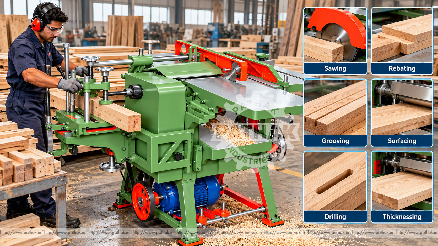
Preparing solid timber usually involves several stages: establishing a flat reference face, producing a square edge, bringing stock to uniform thickness, cutting it to width or length, and machining joints or holes. A Thickness With Surface Planner Combined Circular Saw brings several of these functions into one compact woodworking platform, helping workshops use floor space and a common drive efficiently.
The Pathak Industries PMW-1 is listed with a 13 × 56-inch table, 13-inch gauge width, four blades in the main roller, 40 mm feed rollers, an 8 metre-per-minute thickness feed rate, drilling and tenoning functions, and a 3 HP, 1440 rpm motor requirement. This guide explains the combined machine's functions, recommended stock-preparation sequence, setup, tooling, safety, maintenance, and selection factors.
A combined woodworking machine integrates multiple machining stations into one frame. Depending on the installed accessories and configuration, the PMW-1 supports surface planing, thickness planing, circular sawing, side cutting or grooving, tenoning, and drilling. Each station performs a distinct operation, but the functions share the machine structure and drive arrangement.
This format is particularly useful in general woodworking, furniture workshops, joinery shops, maintenance departments, training facilities, and small production units. It reduces the need for a separate machine for every process, although operators must manage changeovers and use only one approved station or function as the machine instructions permit.
The stored PMW-1 specification includes:
The product table repeats the same cutter label for the 12-inch and 3-inch values, so the exact station and cutter assignment should be confirmed with the supplied machine documentation before tooling is selected.
Surface planing creates the first flat reference face on rough timber. The board is guided across the infeed table and over the rotating cutter block while the outfeed table supports the freshly machined surface. Once one face is flat, an adjacent edge can be jointed square using the fence or gauge.
Successful surfacing depends on flat, aligned tables, sharp and equally set knives, suitable cut depth, secure guarding, and controlled feeding. The operator should read the grain where possible and feed in the direction that limits lifting and tear-out.
Boards that are severely bowed, twisted, split, or too short for safe control require special review and may not be suitable for the standard operation. Surface planing should establish a reference, not attempt to remove all stock in one heavy pass.
After one face has been made flat, thickness planing produces the opposite face parallel to it and reduces the board to the target thickness. The reference face is placed against the thickness table, while powered feed rollers move the stock beneath the cutter block.
The PMW-1 lists 40 mm feed rollers and an 8 metre-per-minute feed rate. Feed must remain positive and even. Dirty or worn rollers, excessive depth of cut, unstable timber, or poor table condition can cause hesitation, marks, or variation.
Remove stock in controlled passes, measuring after the board has cleared the machine. Allow extra material for final finishing where necessary. Multiple boards intended for the same assembly should be processed using a consistent setup to support matching thickness.
The circular saw station is used for straight ripping or crosscutting when equipped and guarded for the intended operation. A fence guides ripping parallel to an established edge, while suitable crosscut support controls stock passing across the blade.
The blade must match the material, cut type, spindle, speed, and machine capacity. Ripping and crosscutting impose different tooth and clearance requirements. A sharp, correctly mounted blade reduces cutting load and helps produce a cleaner edge.
Kickback is a major hazard. The fence, riving arrangement, guards, push devices, and work support must be used according to the machine procedure. Never freehand a cut or place hands in the blade path.
A side-cutter or compatible tooling arrangement may be used for grooves, rebates, and related edge features. Tool width, diameter, spindle fit, guard, fence, and feed direction must match the selected operation. The stored specification lists a 3-inch cutter capacity among the machine values, but the exact assignment and tooling limits should be confirmed.
Grooves and rebates are often produced in more than one pass when the required section is deep or wide. Test pieces help verify location and size before machining finished components.
The PMW-1 lists a 4-inch tenoning capacity and drilling capacity over a 7-inch length. Tenons form structural joints for frames, doors, furniture, and other joinery. Accurate shoulders and cheek thickness depend on correct work support, stops, cutter setup, and reference surfaces.
The drilling or mortising-style station can create holes or slots when fitted with suitable tooling. The work must be clamped or controlled by the approved fixture, and tool alignment should be checked against a test piece before production begins.
Machine capacity does not alone define a safe joint. Timber species, grain direction, component section, tool projection, and required joint dimensions must also be considered.
The exact sequence can vary by product, but maintaining clear reference faces and edges improves dimensional consistency throughout later operations.
The main roller is listed with four blades. All knives must match in size and condition and be set to the same cutting circle. Unequal projection can cause vibration, ridges, poor finish, and unbalanced loading. Knife installation should be completed only with the machine isolated and using the approved setting method.
Replace or sharpen blades when finish deteriorates, feed load rises, or edges show damage. Mixing differently ground knives or using incorrect fasteners can create dangerous imbalance. After maintenance, verify secure clamping and rotate the cutter manually through a complete revolution to check clearance before operation.
Timber should be suitable for machining and conditioned for its intended environment. High or uneven moisture can lead to movement after processing, while very dry or brittle material may chip. Check boards for embedded metal or other foreign material that could damage knives or blades.
Grain direction affects surface finish. Reversing grain, knots, and figured timber may require lighter passes, sharper tools, altered feed direction, or a different finishing method. No machine setting can fully compensate for unstable or defective stock.
The combined machine can support production and preparation for:
Every job should be assessed against the actual station capacity, tool, guarding, work support, and operator procedure.
Several core woodworking processes share one frame, which can suit workshops where space is limited.
A combined drive can reduce the number of separate motors and electrical connections compared with multiple stand-alone machines, subject to the supplied configuration.
Operators can move from stock preparation to selected joint-making operations without maintaining a separate machine for every step.
The machine can support varied components and repair work where flexibility is more valuable than a dedicated high-volume line.
Combined machines require careful changeovers. Guards, fences, tables, cutters, feed arrangements, and dust extraction must be placed correctly for the active function. An accessory left in the path of another station can create a collision or ejection hazard.
Use a written checklist where several operators share the machine. Isolate power before changing tools or rearranging guarded components. After setup, verify all fasteners and clearances and perform a controlled test using suitable scrap material.
Planing and sawing generate large chips and fine airborne dust. Effective extraction improves visibility, limits accumulation, supports tool cooling, and helps keep feed and adjustment mechanisms clear. Connect the correct hood or port for the active station.
Dust from some woods can be hazardous, and fine dust can present a fire or explosion risk. Extraction, housekeeping, ventilation, electrical equipment, and disposal should follow the site's material and risk assessment.
After surfacing, check flatness and look for ridges, tear-out, snipe, and chatter. After thicknessing, measure at multiple points for uniformity and parallelism. Sawed parts should be checked for width, length, squareness, burning, and edge quality.
Grooves, rebates, holes, and tenons require position and size checks against the drawing and mating components. Inspect the first piece after every changeover, tool adjustment, material change, or maintenance action.
This machine includes high-speed knives, a circular saw blade, feed rollers, exposed work movement, and several changeable stations. Only trained personnel should operate it. Guards, fences, riving devices, hold-downs, and extraction hoods must be appropriate to the active operation.
Use push blocks, push sticks, feeders, and work supports where specified. Keep hands away from cutting paths and never reach over or behind moving tooling. Do not remove chips, measure work, or adjust a fence until motion has stopped.
Isolate and verify energy before changing knives, blades, cutters, drilling tools, belts, guards, or machine arrangements. Hearing and eye protection, suitable footwear, and respiratory protection should follow the risk assessment; gloves should not be worn near rotating cutters where they could become entangled.
Daily checks should include cutter and blade condition, guards, fences, table cleanliness, feed rollers, fasteners, belts, extraction, controls, and emergency devices. Remove chips without directing them into bearings, slides, or the motor.
Keep tables clean and protected from corrosion. Inspect knife setting, cutter balance, spindle condition, drive tension, bearings, feed mechanism, and adjustment screws according to the maintenance schedule. Abnormal noise, heat, vibration, or finish change should be investigated promptly.
Periodic checks should cover table alignment, fence squareness, feed-rate performance, electrical connections, foundation fasteners, dust-extraction condition, and safety-device function. Record service and tooling changes to help identify recurring problems.
List the timber species, rough and finished dimensions, largest board, required operations, joint sizes, finish standard, daily volume, available space, power, extraction, and material-handling method. Confirm that table size, gauge capacity, cutter and saw arrangements, thicknessing range, drilling travel, and tenoning capacity suit representative parts.
A combined machine is attractive for flexible production, but workshops running one operation continuously may benefit from a dedicated machine for that bottleneck. Evaluate changeover time, operator training, guarding, tooling availability, maintenance access, and future production growth.
Pathak Industries can review samples and drawings against the PMW-1 configuration. Exact cutter assignments and all capacities should be confirmed in the final technical offer.
The published main table size is 13 × 56 inches, with a 13-inch listed gauge width.
The stored specification lists four blades. They must be correctly matched, balanced, secured, and set to a common cutting circle.
The published feed rate is 8 metres per minute through 40 mm-diameter feed rollers.
The listed requirement is a 3 HP motor at 1440 rpm. Electrical details and the supplied drive arrangement should be confirmed before installation.
Yes. The specification lists drilling over a 7-inch length and a 4-inch tenoning capacity, subject to the supplied tooling and setup.
Thicknessing references one face against the table. Creating a flat initial face helps the opposite surface become parallel rather than reproducing the board's original distortion.
Possible causes include poor work support, table or feed adjustment, excessive depth, roller condition, and the board lifting as it enters or leaves the cutter.
Provide timber type, rough and finished sizes, required operations, largest components, joint details, daily output, power supply, available floor space, extraction, and representative drawings.
The PMW-1 Thickness With Surface Planer Combined Circular Saw provides a compact platform for surfacing, thicknessing, sawing, grooving or rebating, drilling, and tenoning. Its listed 13 × 56-inch table, four-knife roller, 40 mm feed rollers, 8 metre-per-minute thickness feed, and 3 HP motor requirement suit varied workshop preparation and joinery tasks.
Productive use depends on following a logical stock-preparation sequence, maintaining sharp and correctly set tools, completing disciplined changeovers, controlling dust, inspecting the first piece, and applying the correct guarding for every active function. Representative workpieces and drawings should guide final machine and tooling selection.