Head Office
117, Grand Trunk Road, Salkia Howrah-700013, Kolkata, India
 Hitesh PathakWed, Dec 10, 2025
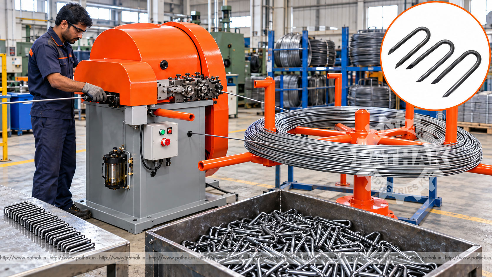
Fence staples appear simple, but producing them consistently requires accurate wire feeding, straightening, cutting, bending, and point formation. Differences in leg length, crown width, wire diameter, or point shape can affect how a staple enters timber and holds fencing wire. A dedicated U Nail Fence Staple Making Machine combines these operations into a repeatable cycle for planned, high-volume production.
The Pathak Industries P UNM-1 is a double-stroke machine designed for wire from 18 to 6 SWG, listed as approximately 1.2 to 4.8 mm diameter. Its published range covers U nails from 1/2 inch to 1-1/2 inches, with 6 to 12 mm distance between the ends and an indicative output of 200 to 250 pieces per minute. This guide explains how the process works, what influences staple quality, how to plan production, and what buyers should confirm before selecting a machine.
A U nail machine converts continuous wire into U-shaped fasteners with two pointed legs joined by a curved or formed crown. These fasteners are commonly driven into wooden posts or structures to retain fencing wire, mesh, and similar materials. Depending on the finished specification, the legs may be parallel or slightly shaped and the crown must provide suitable clearance around the material being secured.
The machine advances a measured wire length, cuts it, forms the crown and legs, and discharges the completed staple. A double-stroke arrangement coordinates forming motions so that both sides are produced consistently. The exact tooling and machine setup determine the finished length, end spacing, bend profile, and point geometry.
Wire is supplied from a coil or payoff arrangement and guided toward the machine. Straightening elements reduce the curvature retained from the coil so that each measured section enters the forming station in a predictable condition. Feed rolls or a mechanical feeding system then advance the required length.
At the forming station, the wire is cut and shaped around dedicated tooling. The process establishes the crown and two legs, while cutting or pointing elements create ends suitable for the intended fastening operation. The formed piece is released into a collection area and the cycle repeats.
Stable production depends on coordination between feed length, cutter condition, die alignment, forming clearance, wire properties, and machine timing. Running at high speed before these elements are verified can create unequal legs, twisted staples, rough points, cracked bends, or dimensional variation.
The listed P UNM-1 configuration provides the following reference values:
These values describe the stated model range. A particular staple may require dedicated dies, cutters, guides, feed settings, or other change parts. Actual output depends on the selected wire, staple size, point design, operator practice, material handling, inspection frequency, and machine condition.
Wire diameter has a direct effect on forming load, tool clearance, finished staple strength, and the timber into which the staple can be driven. A nominal gauge should always be confirmed by measured diameter because gauge conventions and commercial tolerances can differ.
The wire must also have mechanical properties compatible with cutting and bending. Material that is too hard can crack at the crown, damage tooling, or produce unreliable points. Wire that is too soft may deform during packaging or installation. Surface scale, inconsistent coating, rust, and diameter variation can interfere with feeding and shorten tool life.
Galvanized or other coated wire may be selected when corrosion resistance is required. Forming should not remove or severely damage the protective layer. Buyers should provide the wire grade, diameter tolerance, coating type and mass, tensile range, and representative samples when requesting a machine or tooling recommendation.
A complete staple drawing should define more than overall length. Important dimensions include wire diameter, leg length, inside and outside crown width, distance between ends, bend radius, leg parallelism, point length, point angle, and any permitted taper or divergence.
The P UNM-1 lists a 6 to 12 mm distance between ends. The correct value depends on the fencing wire or mesh being retained and the required holding method. A crown that is too narrow may damage the fence wire or prevent correct seating, while excessive width may reduce control during installation.
Point geometry affects penetration force and how the staple follows timber grain. Sharp, symmetrical points support predictable driving, but the approved point style should reflect the customer's fastening specification and safe handling requirements.
The stated rate of 200 to 250 staples per minute describes the machine's indicative cycle capability within a suitable setup. Saleable output per shift must account for coil changes, first-piece approval, collection-bin changes, tool adjustment, inspections, cleaning, planned maintenance, and unexpected stops.
Production managers can track pieces produced, accepted quantity, scrap quantity, downtime by cause, changeover duration, and tool life. These records distinguish machine speed from actual process efficiency. They also show whether the main loss comes from wire quality, coil handling, tool wear, frequent dimensional adjustments, or packaging constraints.
Collection and packaging must be able to keep pace with forming. If finished staples accumulate around the discharge area, they can obstruct the process or create handling hazards. Bins, conveyors, weighing, counting, and packing methods should therefore be included in line planning.
Correctly specified U nails and fence staples may be used for:
The fastener must be suitable for the timber, retained material, environment, installation tool, and applicable standard. A sample installation or customer approval should be completed before volume manufacture for a new application.
A controlled feeding mechanism helps maintain the material length used for each staple, supporting repeat leg dimensions when the wire and tooling remain stable.
Cutting and bending occur in a planned cycle, reducing separate manual operations and the handling between them.
The listed rate of 200 to 250 pieces per minute can support volume orders when raw-material supply, collection, inspection, and packaging are organised around the machine.
Dedicated tooling and recorded settings allow approved sizes to be reproduced. Tool changes still require careful alignment and first-piece validation.
The machine needs a stable, level foundation with adequate space for the wire payoff, operator position, electrical isolation, guards, finished-part collection, maintenance access, and material movement. The shipping envelope should not be mistaken for the full operating footprint.
Wire coils should unwind without tangling, uncontrolled movement, or excessive drag. The payoff position must align with the entry guides and should keep personnel clear of stored wire energy. Finished-staple bins must be located so they can be exchanged safely without reaching into moving equipment.
Electrical supply, earthing, protection, and isolation must match the selected 3 HP drive and control arrangement. Commissioning should be performed by qualified personnel who verify rotation, lubrication, guarding, emergency controls, feed direction, tooling, and discharge clearance.
Inspection should cover wire diameter, overall staple length, individual leg length, distance between ends, crown width, bend condition, point symmetry, surface condition, and freedom from burrs or cracks. A simple approved fixture can speed routine dimensional checks, while calibrated instruments should be used for formal inspection.
Unequal legs often indicate feeding, cutting, or die-alignment problems. An off-centre crown can result from misaligned tooling or inconsistent wire entry. Blunt or ragged points suggest cutter wear or incorrect clearance. Cracking at the bend may be connected to material hardness, surface defects, bend radius, or tool condition.
Checks should occur at startup, after tool or coil changes, at defined production intervals, and whenever sound or machine behaviour changes. Segregate suspect output until its status is established.
U nail machinery contains feed rolls, cutters, forming dies, flywheel or drive motion, sharp wire, and rapidly discharged parts. Operators must be trained and guards must remain in their intended positions. Hands, tools, and clothing should stay clear of all feed and forming zones while the machine can move.
Wire coils store energy and can spring or unwind unexpectedly. Use an approved payoff and handling method, control wire ends, and wear personal protective equipment selected through the site's risk assessment. Eye protection, suitable gloves for material handling, safety footwear, and close-fitting workwear are common considerations.
Before clearing a jam, changing a die, servicing a cutter, or entering a guarded area, isolate all relevant energy and verify the safe state. Emergency stops support response to an incident but are not a substitute for isolation during intervention.
Daily attention should include cleaning wire fragments, inspecting cutters and forming tools, checking guides and feed parts, confirming guard condition, and applying lubrication at the prescribed points. Abnormal vibration, noise, heat, or dimensional drift should be investigated before continuing production.
Cutters and dies are wear components. Their condition directly affects burrs, points, bends, and dimensional repeatability. Tool life should be recorded by wire type and diameter so replacement or sharpening can be planned rather than delayed until quality fails.
Periodic maintenance should include drive and bearing inspection, fastener checks, alignment verification, electrical enclosure cleaning, safety-device testing, and examination of the payoff and straightening system. Record all adjustments so recurring problems can be traced.
Begin with samples or a dimensioned drawing of every staple to be produced. Confirm wire grade, diameter, coating, hardness or tensile range, staple length, crown width, end spacing, point style, tolerance, required output, packaging method, and available electrical supply.
Compare those needs with the machine's approved wire and size range, tooling package, feed and straightening arrangement, production rate, motor, guarding, collection system, installation requirements, training, and spare-parts support. If several sizes are required, ask which components change and how long a normal changeover takes.
Pathak Industries can review representative wire and staple details against the P UNM-1 configuration. Final selection should be based on confirmed samples and written specifications rather than product name alone.
The published range is 18 to 6 SWG, stated as approximately 1.2 to 4.8 mm diameter. Suitability of the actual wire grade and coating should also be confirmed.
The machine information lists sizes from 1/2 inch to 1-1/2 inches, with the metric range shown up to approximately 40 mm. Exact tooling is selected for the required staple.
The published adjustable product range is 6 to 12 mm. Buyers should specify the exact dimension and tolerance needed for their fencing application.
The stated production rate is approximately 200 to 250 U nails per minute. Net accepted output depends on size, wire, tool condition, handling, inspection, and downtime.
The listed model uses a 3 HP motor. The required voltage, phase, frequency, protection, and control arrangement should be confirmed for the installation site.
Galvanized wire may be suitable when its diameter, strength, coating, and forming behaviour match the approved specification. Representative samples are recommended for confirmation.
Possible causes include inconsistent feeding, wire slip, cutter condition, die misalignment, incorrect timing, or unstable wire entry. Stop and correct the cause before continuing saleable production.
Send a staple drawing or sample, wire diameter and grade, coating, staple length, crown width, end spacing, point style, tolerances, daily quantity, packaging method, and plant electrical supply.
The P UNM-1 U Nail Fence Staple Making Machine integrates wire feeding, cutting, bending, and discharge for repeat staple production. Its double-stroke design, 1.2 to 4.8 mm listed wire range, 6 to 12 mm end spacing, 3 HP motor, and indicative output of 200 to 250 staples per minute provide a practical basis for fencing-fastener manufacture.
Consistent results require suitable wire, correctly matched tooling, a controlled first-piece process, routine dimensional checks, safe material handling, and timely maintenance. Clear product drawings and representative samples allow the machine configuration to be matched more accurately to the intended market.