Head Office
117, Grand Trunk Road, Salkia Howrah-700013, Kolkata, India
 Hitesh PathakTue, Dec 16, 2025
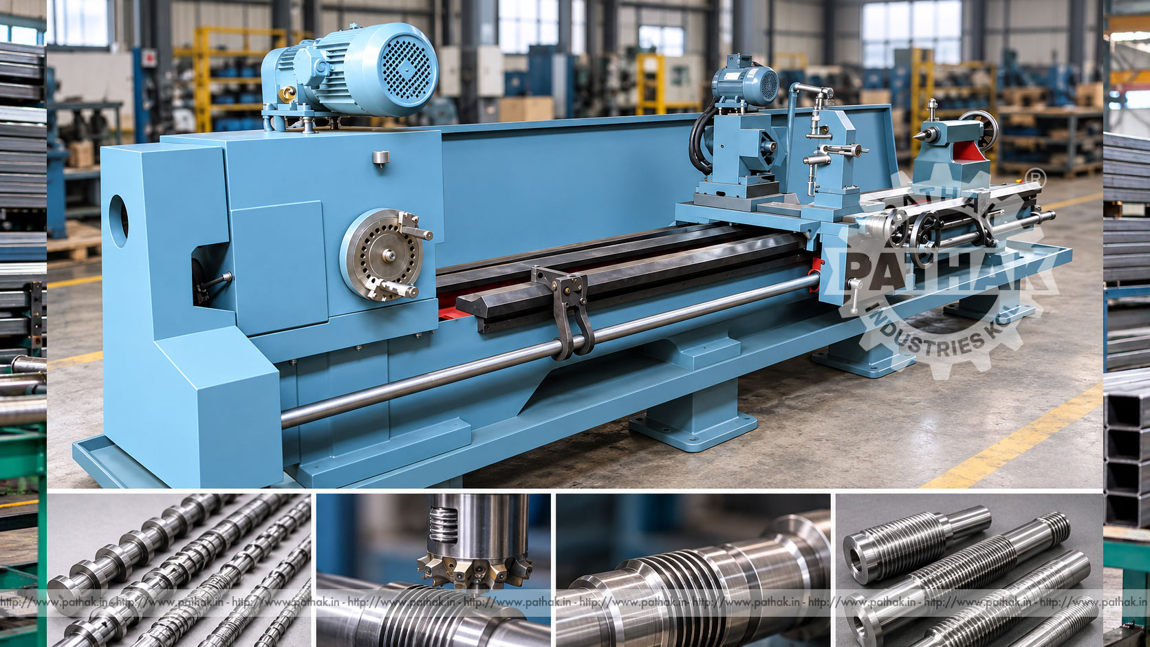
Long lead screws, worms, and precision threaded shafts can exceed the practical range of ordinary threading arrangements. Their production requires coordinated work rotation and cutter travel over a substantial length while maintaining lead, profile, and alignment. A Thread Milling Machine provides a dedicated platform for this controlled relationship between the rotating workpiece and milling cutter.
The Pathak Industries configuration is available with bed lengths from 1,000 to 10,000 mm and admits jobs from 300 to 9,000 mm between centres. Published job diameter is 20–300 mm, spindle bore is 100 mm, and threading lead pitch ranges from 25 to 200 mm. Oil-bath arrangements are listed for both the headstock and milling head, supporting sustained operation when the machine is correctly installed and maintained.
A thread milling machine produces helical forms by coordinating a rotating multi-edge cutter with controlled workpiece rotation and longitudinal movement. Unlike single-point turning, the milling cutter removes material through multiple cutting edges. The exact arrangement depends on the thread form, lead, work length, and selected machine configuration.
The process is suited to external threads and related helical forms on long or specialised components. It is distinct from CNC thread milling inside a general machining centre; this machine is built around supported shaft work, low controlled spindle rotation, long travel, and a dedicated milling head.
The workpiece is mounted between centres or held through an approved spindle and support arrangement. It rotates slowly while the milling cutter turns at its cutting speed. Machine gearing or electronic drive coordinates work rotation and carriage movement to generate the specified helix.
The cutter is set to the correct centre height, profile orientation, and depth. One or more passes remove material until the required thread form and dimension are reached. Long components need consistent support and alignment so that deflection does not create taper or lead error.
The listed bed range is 1,000–10,000 mm, with 300–9,000 mm admitted between centres. This broad range indicates that the machine is configured around the required work length rather than treated as a single fixed size. Bed width is listed as 375 or 450 mm according to configuration.
Longer work increases the importance of foundation quality, bed alignment, steady supports, lifting, and material handling. Selection should be based on the maximum raw length, finished threaded length, unthreaded holding areas, tool run-out space, and inspection access.
The published job-diameter range is 20–300 mm, while the spindle bore is listed at 100 mm. A job within the diameter range may not necessarily pass through the spindle. Chucking, centre support, tailstock capacity, and cutter clearance must all be checked.
Large diameter or long slender work creates different challenges. Heavy shafts need adequate loading and support capacity. Slender screws can deflect under cutter load and may require one or more correctly adjusted steady rests.
The listed threading lead pitch is 25–200 mm. Lead is the axial distance advanced by the helix in one workpiece revolution. For a single-start thread, lead equals pitch; for a multi-start thread, lead equals pitch multiplied by the number of starts.
That distinction must be clear on the drawing. Tool profile, machine settings, work rotation, and longitudinal feed must be planned from the specified lead and number of starts. Ambiguous thread terminology can produce a component that looks threaded but will not mate or transmit motion correctly.
The product page describes an oil-bath headstock with electronic spindle drive. Main work-spindle speed is listed from 0.1 to 1 rpm, appropriate to the slow controlled rotation used while the milling cutter generates a long-lead helix.
The main spindle drive is listed at 3 HP. Electronic control can support controlled rotational behaviour, while the oil bath lubricates internal elements. Oil level, grade, contamination, temperature, and leakage should be monitored according to the supplied maintenance instructions.
The milling head is also specified with oil-bath lubrication. Its listed capacity is 25–40 mm, with an ISO 40 spindle interface and a 2 HP motor. Cutter selection must match the required thread form, material, capacity, and spindle arrangement.
Cutter runout, edge condition, mounting cleanliness, and projection directly influence profile and finish. The tool should be balanced and secured according to the manufacturer’s procedure. A damaged or incorrectly mounted cutter must never be brought into production.
The source lists longitudinal feed from 0.1 to 200 mm and a 50 mm diameter lead screw with 2 TPI pitch. The machine’s feed and drive elements establish the cutter’s axial relationship to work rotation.
Backlash, wear, contamination, lubrication, and alignment can affect consistency over a long travel. Guideways and screws should be kept clean, and reversal or compensation procedures should follow the machine documentation rather than informal operator correction.
The listed tailstock spindle diameter is 50 or 75 mm, with MT4 or MT5 taper options noted for the spindle sleeve. Correct centre selection and tailstock alignment help establish the work axis and carry axial support.
Centre pressure must be sufficient without distorting the work or overheating the centre. Long jobs require planned steady-rest positions. Supports should carry the shaft while allowing free rotation and cutter passage.
A dedicated thread milling machine can support:
Suitability depends on material, hardness, thread form, pitch or lead, number of starts, accuracy, finish, and batch quantity. Actual component drawings should be reviewed before machine configuration or tooling is selected.
The cutter must reproduce the specified thread flank angle, root, crest, and radius while allowing for the helical geometry. A tool that appears correct in a simple end view may generate profile error when applied at the wrong helix relationship.
Tool design should therefore use the component specification and machine arrangement. Cutter material and coating, where applicable, must match the work material and cutting conditions. Regrinding requires profile control, not only restoration of a sharp edge.
A shaft can bend under its own weight or the radial load of milling. Deflection changes depth and thread geometry along the component. Support positions, cutter engagement, depth per pass, and cutting direction must be developed to keep the work stable.
Steady rests should be aligned to the true axis and adjusted without excessive pressure. As the cutter advances, support locations may need to accommodate tool travel according to the approved process. Work straightness should be checked before and after machining.
Thread milling generates chips along a helical groove. A suitable cutting fluid can cool the tool and work, lubricate the cut, and help move chips away. Fluid selection must suit the work material, cutter, and plant requirements.
Chips should not be cleared by hand near moving parts. Guards and collection arrangements need to contain ejected material while leaving required inspection access. Wrapped or compacted chips must be removed only after safe isolation.
Inspection can include major diameter, minor diameter, pitch diameter, lead, cumulative lead error, flank angle, runout, surface finish, and number-of-start relationship. The drawing and service determine which characteristics are critical.
Long threads may require measurements at several axial positions. Suitable gauges, measuring wires, profile equipment, lead measurement, or mating checks may be used under the inspection plan. A visual check alone cannot confirm lead accuracy.
Configurable bed length and between-centres capacity support shafts beyond the working range of ordinary shop lathes.
Slow work rotation and coordinated longitudinal movement provide the relationship needed for large thread leads.
A dedicated oil-bath milling head carries suitable multi-edge cutters for productive material removal.
Bed width, length, tailstock, cutter capacity, and support arrangements can be selected around documented work requirements.
Long rotating work, cutters, chucks, centres, lead screws, and travelling assemblies create serious hazards. The full work envelope must be guarded, and unsupported projecting stock must never be allowed to rotate. Operators should remain clear of the cutter and shaft during movement.
Only trained personnel should set or operate the machine. Electrical and mechanical energy must be isolated before tool changes outside the approved method, support adjustment, chip removal, or maintenance. Heavy components require rated lifting equipment and planned rigging.
Daily checks include headstock and milling-head oil levels, leakage, cutter and holder condition, centres, supports, guards, guideways, lead screw, coolant, and controls. Chips should be removed with safe tools and exposed sliding surfaces cleaned and protected.
Scheduled work should cover oil condition, bearings, drive alignment, electronic spindle control, feed mechanisms, backlash, tailstock alignment, support wear, fasteners, electrical connections, and foundation geometry. Long beds benefit from periodic alignment verification.
Provide a dimensioned drawing, raw and finished length, diameter, material and hardness, thread form, pitch, lead, number of starts, tolerances, finish, batch size, and output target. Confirm the required bed length, between-centres capacity, supports, cutter, head interface, spindle bore, and inspection method.
Also plan foundation, floor space, loading, power, coolant, guarding, operator training, service access, and transport. Pathak Industries can configure the thread milling machine around representative components rather than relying on a general model description.
The source lists 20–300 mm diameter and 300–9,000 mm between centres, depending on configuration.
Published bed length ranges from 1,000 to 10,000 mm, with 375 or 450 mm bed-width options.
The listed threading lead pitch range is 25–200 mm. The drawing must clarify pitch, lead, and number of starts.
The product page lists a 100 mm spindle bore, subject to the selected configuration and workholding.
The source lists 25–40 mm capacity, an ISO 40 interface, oil-bath lubrication, and a 2 HP milling-head motor.
Slow controlled rotation coordinates with axial cutter movement to generate the specified long-lead helix.
They are held between approved centres or workholding and supported with aligned steady arrangements selected for length, diameter, mass, and deflection.
Provide component drawings, material, length, diameter, thread profile, lead, starts, tolerances, batch size, lifting plan, utilities, and inspection requirements.
The Pathak Industries thread milling machine provides a configurable platform for long lead screws, worms, and specialised external threads. Its long-bed options, 20–300 mm job range, 100 mm spindle bore, oil-bath headstock and milling head, and 25–200 mm lead capability address demanding shaft work. Accurate results require precise setup, rigid tooling, controlled support, validated helix settings, thorough inspection, and disciplined maintenance.