Head Office
117, Grand Trunk Road, Salkia Howrah-700013, Kolkata, India
 Hitesh PathakFri, Jun 7, 2024
Internal threads allow bolts, studs, fittings, and fasteners to connect components securely. Producing those threads repeatedly requires more than placing a tap into a drilled hole. The hole must be prepared correctly, the tool must remain aligned, the workpiece must be held securely, and the tap must enter and reverse without being subjected to avoidable side load. A dedicated tapping machine provides an organized workstation for controlling this important manufacturing operation.
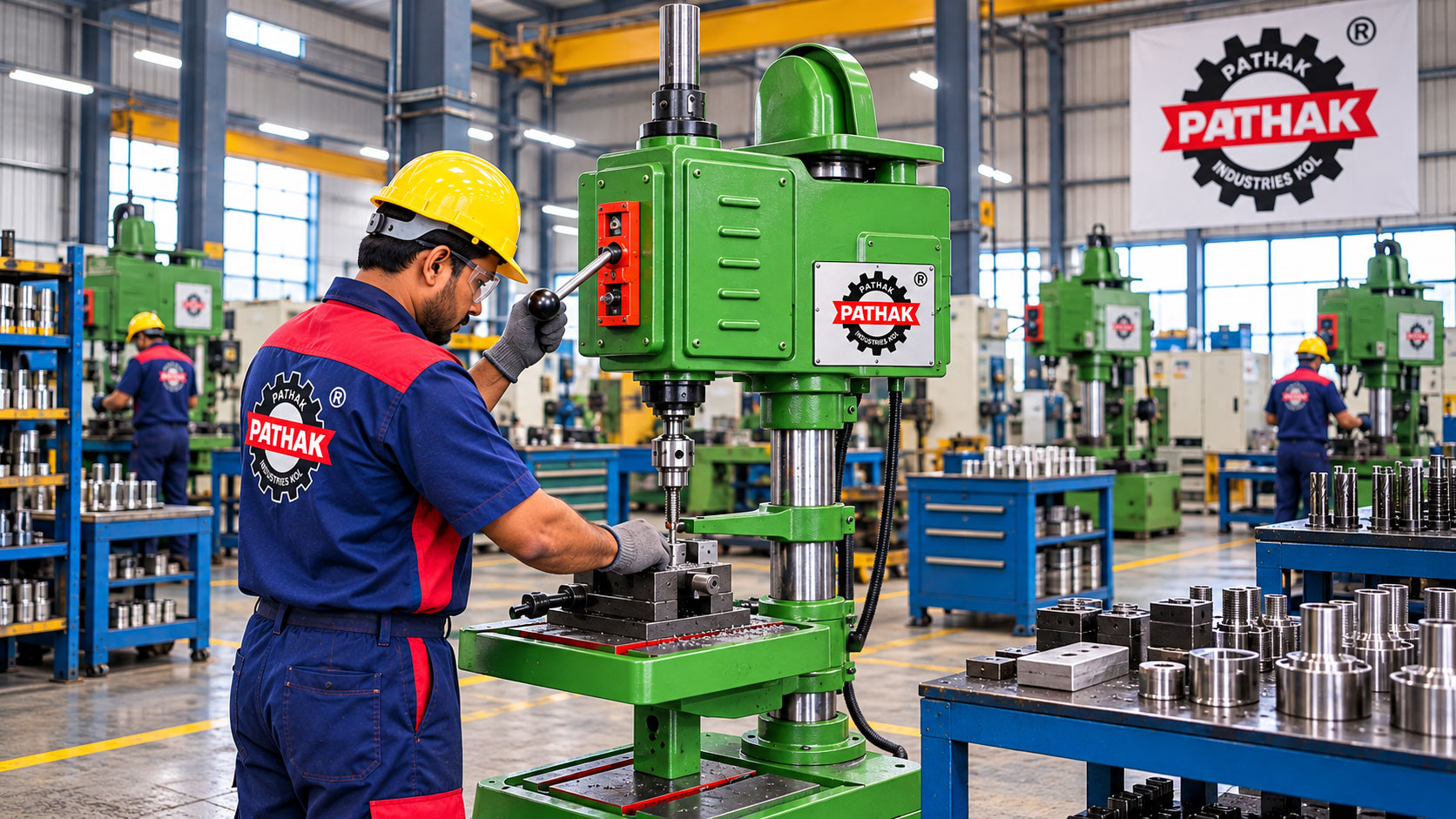
The Tapping Machine offered by Pathak Industries is intended for forming internal threads in prepared holes. Its product page lists TP12 and TP6 models with different tapping capacities, drilling capacities, travels, speeds, worktable sizes, dimensions, and approximate weights. This guide uses that published information to explain machine operation, applications, selection, setup, and maintenance.
A tapping machine drives a tap into a correctly prepared hole so that the cutting edges form an internal thread. It then reverses the tool to withdraw it from the workpiece. Unlike an ordinary drilling operation, tapping must maintain a relationship between tool rotation and axial movement. The tap follows the thread it creates, which makes alignment, tool condition, hole preparation, lubrication, and controlled reversal especially important.
Typical workpieces include plates, castings, fittings, brackets, housings, fabricated parts, and assembly components. A tapping machine can serve a general workshop, an assembly area, a fabrication unit, or a batch-production cell. Suitability depends on the thread size, material, hole type, component geometry, required output, and the selected model’s documented capability.
The process begins with a hole of the correct size and condition. The workpiece is positioned and restrained so that it cannot rotate or shift. A suitable tap is installed and aligned with the hole axis. During the forward part of the cycle, the spindle drives the tap into the hole. At the required depth, the machine reverses so the tap follows the newly formed thread back out.
The setup should prevent misalignment between the spindle, tap, and prepared hole. If the tap enters at an angle, loading can become uneven and the resulting thread may not meet the intended geometry. Blind holes also require careful depth planning because the tap cannot continue beyond the available space. Through holes provide a different chip path, but they still require appropriate tooling and process control.
A tap cannot compensate for an incorrectly sized or poorly positioned hole. The drilling stage establishes the material that remains for thread formation. Hole preparation must therefore follow the selected tap and thread requirement. Burrs, chips, scale, or a damaged entry can interfere with tool engagement. Cleaning and checking the hole before tapping helps reduce avoidable problems.
Controlled reversal is a defining part of the tapping cycle. The machine must withdraw the tap without damaging the thread or applying unnecessary bending force. The product page lists three forward speeds and three reverse speeds for each model. Speed selection should be based on the workpiece material, tap, thread, hole form, lubrication, and machine instructions rather than using one setting for every job.
The TP12 model has a published tapping capacity of 12 mm and drilling capacity of 8 mm. Its spindle travel is listed as 75 mm. The three forward speeds are 350, 620, and 1,100, while the reverse-speed range is listed as 420, 745, and 1,315. Its worktable is published as 190 × 220 mm, overall height as 1,245 mm, overall width as 370 mm, front-to-back dimension as 600 mm, and approximate weight as 120 kg.
The TP6 model has a published tapping capacity of 6 mm and drilling capacity of 3 mm. Its listed travel is 60 mm. Three forward speeds of 480, 750, and 1,400 are provided on the product page. Its worktable is listed as 150 × 150 mm, overall height as 650 mm, width as 270 mm, front-to-back dimension as 540 mm, and approximate weight as 50 kg.
These values indicate two different capacity and footprint options. They should be used for initial comparison, not as a substitute for a complete application review. Buyers should confirm the required thread, hole, tool, material, workpiece clearance, electrical supply, production rate, and current model specification before ordering.
Fabrication shops frequently require threaded holes for covers, supports, guards, mounting plates, frames, and brackets. A dedicated tapping station can separate thread production from other fabrication steps and provide a consistent place for tool storage, setup, and inspection.
Machine housings and cast components often use internal threads for covers, bearing supports, fittings, or assembly hardware. The casting must be positioned securely, and the prepared hole must align with the intended thread axis. Surface irregularity and component geometry should be considered when planning support and clamping.
Threaded fittings and small assembly parts may be produced repeatedly in batches. A tapping machine can help organize the sequence when the same thread is required across many similar components. Jigs, stops, or fixtures may improve positioning where suitable, but they must be designed for the actual part and operation.
Maintenance teams may need to create a replacement part, restore a prepared hole using an approved repair method, or manufacture a bracket for plant equipment. The condition of the existing component should be assessed before machining. A damaged thread does not automatically mean that retapping is technically suitable.
A dedicated machine keeps tapping centered on controlled alignment and reversal. It can reduce the handling associated with repeatedly adapting another workstation and can provide a consistent location for suitable production jobs. Multiple speed options allow the process to be adjusted for different tools and materials within the model’s capabilities.
For batch work, repeatable positioning and documented settings can help reduce variation between components. The benefit still depends on disciplined preparation: the correct hole, sharp tap, appropriate lubrication, secure workholding, and inspection remain essential. Automation or powered movement cannot correct an unsuitable tap or inaccurate starting hole.
The tap must match the required thread form and workpiece material. Tool geometry, coating, flute arrangement, and intended use can influence chip behavior and cutting load. Blind-hole and through-hole jobs may require different approaches. Worn or damaged taps should be removed from service because deteriorated cutting edges can increase load and reduce thread quality.
Suitable cutting fluid or lubricant may reduce friction, control heat, support tool life, and improve the tapping process where appropriate for the material. Chips should be controlled and removed safely after the spindle stops. Hands should not be used to clear sharp swarf from the tool or work area.
Start with the largest and smallest threads to be produced. Then review the workpiece material, prepared-hole size, hole depth, blind or through configuration, component dimensions, required clearance, batch quantity, worktable needs, spindle travel, speed options, and available floor space. The published TP12 and TP6 capacities provide a useful starting point for this comparison.
Buyers should also consider workholding. A small component may need a vice or dedicated fixture, while an irregular casting may require a different support arrangement. The selected method must restrain the work without distorting it or obstructing the tapping path. Electrical supply, operator access, guarding, maintenance space, tooling availability, and service requirements should form part of the purchasing decision.
Before starting, inspect the machine, tap, holder, work support, guards, controls, and working area. Confirm that the workpiece is secure and the tap is aligned with the hole. Select the operating setting according to the job and verify that the required depth can be achieved without collision. A trial on representative material can help validate a new setup before a production batch begins.
During operation, the operator should watch for unusual noise, tool deflection, poor chip behavior, excessive heat, or inconsistent reversal. The machine should be stopped if the process does not appear normal. Finished threads can be checked using the inspection method specified for the component.
Keep the worktable, spindle area, and surrounding floor clean. Inspect the tap holder, belts, fasteners, moving parts, controls, wiring, guards, and lubrication points at the intervals specified for the machine. Worn transmission components or loose mountings can affect operation and should be addressed before production continues.
Rotating tooling presents entanglement and contact hazards. Hair, jewelry, loose clothing, and hands must remain clear of the spindle and tap. The workpiece should never be held by hand during powered tapping. Before adjustment or maintenance, stop and isolate the machine using the applicable procedure.
It forms internal threads in correctly prepared holes by driving a tap forward in alignment with the hole and reversing it for withdrawal.
The TP12 has published tapping and drilling capacities of 12 mm and 8 mm, while the TP6 is listed at 6 mm and 3 mm. They also differ in travel, speed ranges, worktable size, overall dimensions, and approximate weight.
The appropriate method depends on the tap, thread, material, depth, chip control, and model capability. Blind holes require particular attention to available depth and chip evacuation.
The tap can transmit torque into the component. Secure workholding prevents the part from rotating or shifting and helps maintain alignment with the spindle.
Provide the thread sizes, workpiece materials, hole depths, blind or through-hole requirements, component dimensions, batch quantities, available electrical supply, and any fixture or production requirements.
A Tapping Machine creates an organized process for producing internal threads in plates, castings, fittings, and fabricated components. The Pathak TP12 and TP6 models provide different capacities and footprints for different workshop needs. Reliable results come from matching the machine to the actual thread requirement, preparing the hole correctly, selecting suitable tooling, maintaining alignment, securing the workpiece, choosing appropriate operating settings, and following a disciplined inspection and maintenance routine.