Head Office
117, Grand Trunk Road, Salkia Howrah-700013, Kolkata, India
 Hitesh PathakTue, Aug 17, 2021
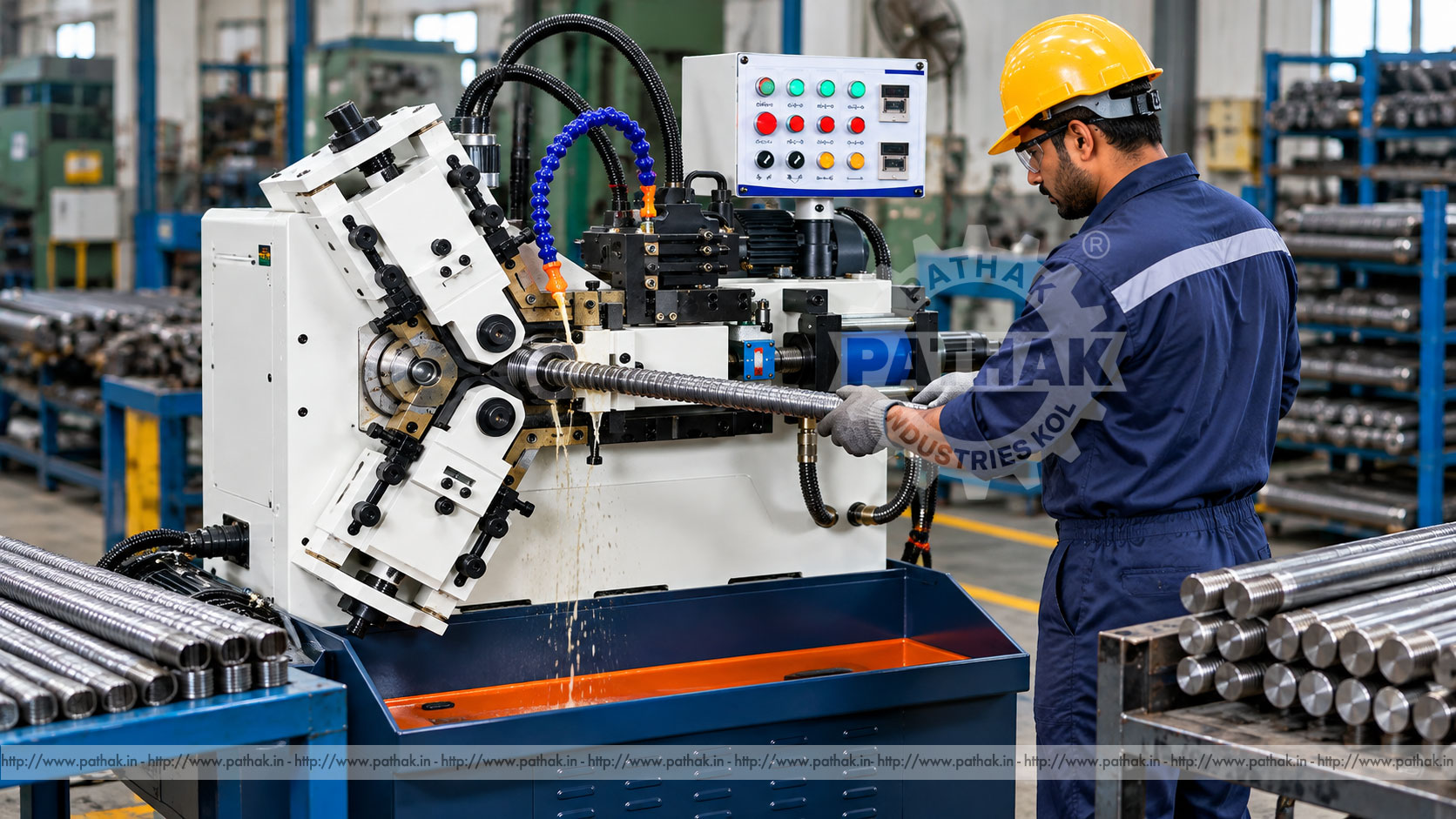
External threads can be manufactured by cutting material away or by displacing it under controlled pressure. For suitable materials and production requirements, rolling offers a chipless method that forms the thread profile using hardened dies. A Round Die Three Roll Threading Machine uses three coordinated round dies to support and form a cylindrical workpiece.
The three-roll arrangement is particularly useful where balanced support, concentric forming, surface quality, and consistent production are important. This guide explains the process, tooling, setup, applications, quality controls, safety, maintenance, and the information buyers should evaluate before selecting a machine.
A round die three roll threading machine is a cold-forming machine that produces external threads and related profiles by pressing three rotating dies against a prepared blank. The dies contain the inverse form of the required thread. As they rotate and feed into the work, material flows plastically into the die profile.
Unlike thread cutting, the process does not create the thread by removing a continuous chip. Correctly applied rolling can provide high production rates, good surface finish, and favourable grain flow. Results depend on the blank material, blank diameter, die geometry, machine setup, lubrication, forming load, and required thread specification.
The workpiece is positioned at the correct centre relative to three round dies. The dies rotate in a synchronised relationship and close around the blank according to the machine cycle. Their profiles progressively displace material from the thread root region toward the crests until the target form and effective diameter are reached.
With three points of contact arranged around the component, the work receives balanced support during forming. The exact cycle may be through-feed, in-feed, plunge, or another machine-specific method depending on part geometry and die design. Setup and operation must follow the supplied machine and die instructions.
Thread cutting removes material with a single-point tool, die head, chaser, or milling cutter. Thread rolling reshapes the blank without intentionally removing material. This distinction affects the required blank size, material behaviour, surface condition, tooling, and inspection strategy.
Potential benefits of rolling include:
Rolling is not appropriate for every material, thread, or component. Hardness, ductility, wall thickness, feature location, batch quantity, and tolerance must be reviewed before choosing the process.
Three dies support the work around its circumference and distribute forming forces from multiple directions. This arrangement can help maintain centring and roundness on appropriate components. It can also be useful for hollow or longer work when the process, wall section, support system, and forming load are properly engineered.
The advantage depends on accurate die matching and alignment. Differences in die phase, height, diameter, speed, or penetration can produce lead errors, out-of-round threads, double tracking, poor fill, or excessive load.
A typical machine may include:
Machine configurations vary. Current spindle diameter, rolling force, work range, speed, motor power, die dimensions, and automation options should be confirmed for the proposed component.
Rollability is controlled by ductility, hardness, tensile strength, microstructure, surface scale, heat treatment, and the amount of deformation required. Many suitable carbon steels, alloy steels, stainless steels, aluminium alloys, copper alloys, and other formable materials may be considered, but each application needs process confirmation.
Material that is too hard or brittle may crack, flake, or overload the tooling. Excessively soft or inconsistent material can produce poor size control or surface pickup. Material certification and a representative trial are advisable for critical work.
A rolled-thread blank is normally smaller than the finished major diameter because material moves outward to form the crests. The correct blank diameter depends on thread form, pitch, material behaviour, die design, and the target pitch diameter.
Even a small blank-diameter variation can change crest fill, pitch diameter, rolling pressure, and die life. Blank preparation should therefore control diameter, roundness, straightness, surface finish, and chamfer geometry. The die supplier's starting recommendation should be validated through trials and inspection.
A consistent lead chamfer helps the dies engage the blank progressively. A poor chamfer can create a folded start, incomplete first threads, excessive die loading, or unstable entry. Chamfer angle and length must suit the thread and rolling method.
Remove burrs without damaging the controlled blank diameter. Oil, scale, dents, and deep tool marks should also be addressed because rolling can reproduce or intensify surface defects.
The dies must match the thread form, nominal diameter, pitch or threads per inch, helix, material, rolling method, and machine spindle arrangement. A three-die set is manufactured and identified as a matched group and should remain together.
Die material, heat treatment, coating, face width, bore, keyway, and lead design influence performance. Dies should be inspected before installation for damage, wear, corrosion, embedded material, and identification. Mixing unmatched dies risks phase and profile errors.
Clean the spindles, die bores, keys, faces, spacers, and clamping hardware. Dirt or burrs beneath a die can create runout. Install each die in its specified position and orientation, then secure it using the approved torque and method.
Phasing aligns the thread starts of the three dies so they enter the same helical track. Incorrect phasing can create double starts, crossed impressions, damaged crests, vibration, and high load. Use the manufacturer's timing marks, setting gauge, or prescribed procedure rather than visual estimation.
The correct die speed depends on material, thread diameter, pitch, die design, lubrication, part length, and machine capability. Excessive speed can increase heat and reduce control. Inappropriate low speed may affect productivity or material flow in some applications.
Forming pressure or die penetration must be sufficient to achieve the required profile without overfilling, damaging the surface, distorting the component, or overloading the machine. A longer dwell does not automatically correct a poor blank or die setup.
Record successful parameters for each part number, material condition, and die set. Repeatability improves when setup values are based on controlled process data rather than operator memory.
Thread rolling creates high contact pressure between the dies and workpiece. The correct rolling fluid reduces friction, controls temperature, helps prevent material pickup, protects the formed surface, and supports die life.
Fluid selection must suit the work material, die coating, later cleaning or plating, operator exposure controls, and environmental requirements. Maintain concentration where applicable, remove contamination, clean filters, and direct flow consistently into the forming zone.
Three-roll threading machines can be considered for suitable:
Suitability must be established from the complete component drawing and process requirements, not from nominal thread diameter alone.
Inspection may include:
Gauge condition and calibration are essential. A ring gauge provides a valuable functional check but may not explain the source of a process error. Measurement over wires, optical inspection, profile analysis, or laboratory testing may be required depending on the specification.
Possible causes include an undersized blank, insufficient penetration, incorrect die profile, low forming load, short dwell, or unsuitable material condition. Do not increase pressure before checking the blank and tooling.
The blank may be too large or the dies may close too far. Confirm calibration, temperature, die wear, and measurement technique before adjusting the cycle.
Double or crossed impressions can result from incorrect die phasing, unstable entry, blank movement, poor support, damaged lead sections, or incorrect die matching.
Review material ductility and hardness, incoming surface defects, excessive deformation, blank preparation, die condition, and lubrication. Critical defects require engineering and quality review rather than cosmetic acceptance.
Contaminated fluid, material pickup, worn dies, scale, incorrect speed, unstable support, or unsuitable blank finish can mark the thread flanks and crests.
The dies, spindle drives, hydraulic system, and rotating component create severe crush, entanglement, ejection, and fluid-injection hazards. Operators must receive machine-specific training and follow the approved risk assessment.
Daily checks should cover lubrication level and flow, hydraulic oil and leaks, die clamping, work support, guarding, controls, abnormal noise, and cleanliness. Remove scale and debris without damaging spindle faces or guides.
Planned maintenance should inspect spindle bearings, gears and couplings, hydraulic pressure and filtration, seals, hoses, electrical connections, sensors, guideways, alignment, and foundation fasteners. Contaminated fluid and loose die mountings can quickly reduce quality and tooling life.
Maintain records for each die set, including part numbers, material, settings, production quantity, inspection results, regrinding, and observed wear. Trend information helps schedule service before defects appear.
Production cells may add magazines, feeders, conveyors, loading devices, length stops, part sensing, ejection, and inspection. Automation should be justified by batch volume, part variety, cycle time, loading risk, and changeover requirements.
Long bars require stable infeed and outfeed support aligned with the rolling centre. Unsupported material can bend, whip, damage the thread, or create serious danger. Handling equipment must be rated for the component weight and length.
Provide the manufacturer with complete component and production information:
Compare rolling force, work range, spindle and die dimensions, die speed, feed method, motor and hydraulic power, support arrangement, control features, guarding, footprint, and installation requirements. Representative trials are valuable for new materials or critical parts.
No. Thread rolling forms the profile by controlled plastic displacement between hardened dies rather than by removing a thread-shaped chip.
Three dies provide multiple, balanced contact points around suitable cylindrical work, supporting centring and controlled forming when correctly aligned and phased.
No. Material hardness, ductility, microstructure, surface condition, and required deformation must be suitable. Confirm the grade and condition through process review and trials.
Normally it is smaller because displaced material flows outward to form the crests. The correct starting diameter comes from die and process recommendations followed by trial inspection.
Common causes include incorrect die phasing, unstable entry, poor support, work movement, mismatched dies, or damaged die lead sections.
Some hollow components may be suitable, but wall thickness, material, diameter, internal support, and forming pressure must be evaluated to prevent collapse or distortion.
Methods may include GO/NO-GO ring gauges, diameter measurement, measurement over wires, optical or profile inspection, runout checks, and specified mechanical or metallurgical tests.
Send the component drawing, thread specification, blank details, material and hardness, batch volume, quality requirements, utilities, handling needs, and required tooling and gauges.
A Round Die Three Roll Threading Machine provides a balanced chipless process for producing suitable external threads and profiles. Its productivity and quality depend on the complete system: controlled blanks, matched and correctly phased dies, stable support, suitable speed and pressure, effective lubrication, disciplined inspection, and safe operation.
Machine selection should begin with the component drawing and material condition rather than a nominal diameter alone. Confirm rolling force, work range, die arrangement, quality requirements, handling, output, and service support against the current technical offer before finalising a configuration.