Head Office
117, Grand Trunk Road, Salkia Howrah-700013, Kolkata, India
 Hitesh PathakTue, Mar 17, 2026
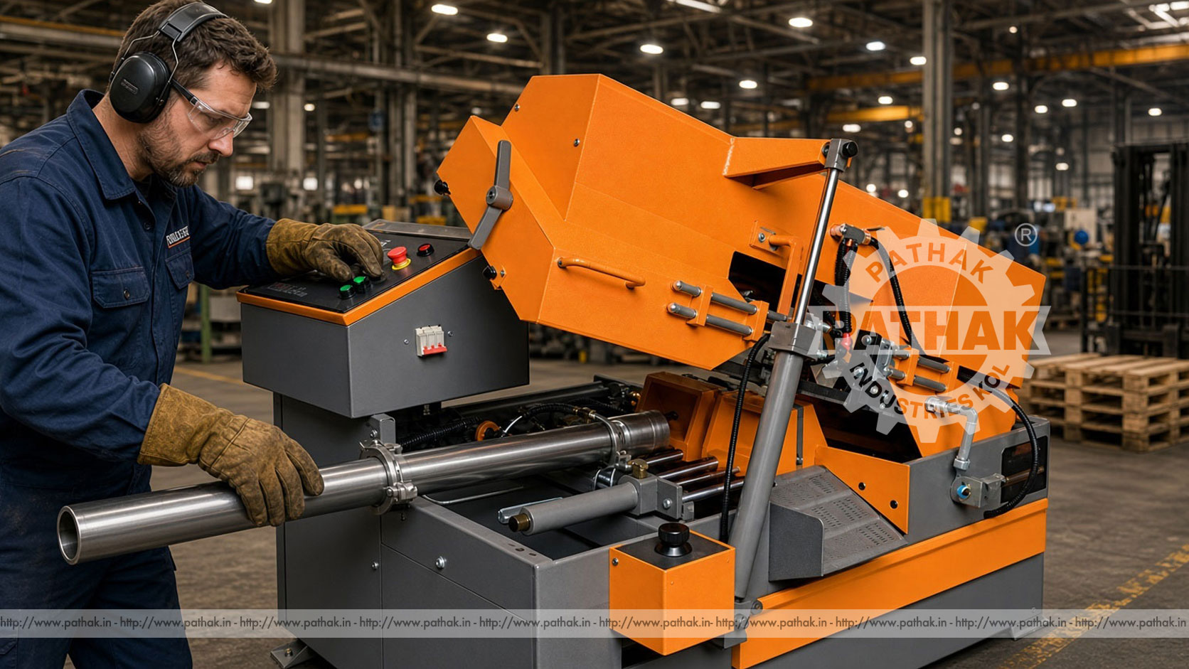
Preparing metal stock accurately is the first step in many machining and fabrication workflows. Bars, tubes, and profiles must be cut to manageable lengths before turning, milling, drilling, welding, or assembly. A Horizontal Metal Cutting Bandsaw Machine performs this work with a continuous loop blade that travels through supported material while the saw frame feeds downward in a controlled direction.
The Pathak Industries PDC model has a published cutting capacity of 175 mm for round stock and 150 × 150 mm for square stock. Its listed blade size is 3000 × 27 × 0.9 mm, with blade speeds of 20, 40, and 60 metres per minute. A 1 HP drive motor, 0.50 HP hydraulic motor, and 0.15 HP coolant pump are included in the stored specification. These values provide a useful basis for selection, but material grade, section shape, wall thickness, tooth pitch, feed, and clamping still determine practical cutting performance.
A horizontal bandsaw uses a long, toothed blade welded into a continuous loop. The blade runs around wheels inside the saw frame and is guided across the cutting zone. The workpiece lies horizontally in a vice or support system, while the blade descends through its cross-section.
Because only a narrow kerf is removed, bandsawing can make efficient use of stock. The continuous blade distributes cutting action across many teeth, and the horizontal arrangement makes it practical to support long bars and profiles on roller stands. The machine is commonly positioned near material storage or at the start of a fabrication line.
The operator measures the required length, moves the stock onto the supports, and positions it against a stop or cutting reference. The workpiece is clamped securely so it cannot rotate or shift. After blade condition, speed, coolant, and guide positions are checked, the saw frame is lowered into the material under the configured feed control.
The blade teeth form chips as they pass through the work. Coolant reaches the cutting zone to help control heat, lubricate the contact, and carry chips away where appropriate. At the completion of the cut, the blade clears the stock and the saw frame returns or is raised for unloading and the next length.
Model PDC is listed for round material up to 175 mm and square material up to 150 × 150 mm. These are shape-specific envelope values. A rectangular profile, bundled work, or irregular section may have different limits depending on vice opening, blade clearance, and how it sits in the machine.
Capacity does not automatically describe cutting rate. A solid 175 mm bar presents far more material to the blade than a thin-wall tube of the same outside diameter. Alloy, hardness, heat treatment, interrupted surfaces, and scale also influence blade choice and cycle conditions. Submit representative stock details when confirming suitability.
The product table specifies a blade measuring 3000 mm long, 27 mm wide, and 0.9 mm thick, with carbon or bi-metal construction listed. The machine must use the correct blade dimensions so it can track on the wheels, fit the guides, and operate within its tensioning range.
Carbon blades can suit selected general cutting work, while bi-metal blades combine a flexible backing with a harder tooth edge for many metal-cutting applications. The correct choice depends on the workpiece material, hardness, section, quantity, and desired blade life. Blade construction should be matched to the job rather than chosen solely by purchase price.
Tooth pitch describes the number and spacing of teeth along the blade. It should keep an appropriate number of teeth engaged in the material. If too few teeth are engaged, individual teeth can overload and strip. If too many are engaged, the small gullets may pack with chips and reduce cutting efficiency.
Thin-wall tubes and profiles generally need finer teeth than large solid sections. Variable-pitch blades can help reduce vibration across changing engagement. When cutting bundles, pitch must account for the repeated entry and exit at individual pieces. Use the blade supplier’s selection guidance for the actual section and material.
The PDC lists 20, 40, and 60 m/min blade speeds. Speed influences heat, tooth loading, chip formation, and blade life. Harder or less machinable materials often require a lower speed, while suitable softer stock may permit a higher setting. The correct value must also reflect blade construction and coolant conditions.
A higher speed is not automatically more productive. If teeth overheat or wear rapidly, the machine may spend more time changing blades and correcting poor cuts. Begin with recognised cutting data and observe the chips, sound, blade condition, and squareness. Change one parameter at a time so the effect can be understood.
The specification includes a 0.50 HP hydraulic motor. The hydraulic system supports controlled saw-frame movement according to the machine arrangement. Stable feed helps the blade maintain effective tooth engagement without dropping aggressively into the stock.
Excessive feed can overload teeth, cause blade deflection, and produce a rough or angled cut. Feed that is too light may cause rubbing instead of proper chip formation, which can also shorten blade life. Feed should be adjusted for cross-section, material, blade pitch, and blade condition, with the work securely clamped.
The listed coolant pump is 0.15 HP at 440 volts. Coolant should be directed at the cutting area in the manner intended by the machine. Correct concentration and flow help control heat, lubricate the blade, and move chips away. The coolant selected must suit both the work material and saw system.
Chips can accumulate around guides, vice surfaces, the coolant return, and the machine base. Regular removal prevents them from affecting clamping, coolant circulation, or moving parts. Use a brush or chip tool after isolation; sharp swarf should never be cleared with bare hands.
A bandsaw vice should grip the stock firmly without crushing thin-wall sections. Round material needs protection against rotation. Irregular shapes may require packing or a dedicated support arrangement that remains clear of the blade. Clamping close to the cutting line helps reduce vibration.
The product record lists two bar stands, each with published dimensions of 1150 × 300 × 480 mm. Supports should align with the machine bed so long stock remains level and does not twist the cut. Additional roller supports may be required for material longer or heavier than the standard arrangement can safely handle.
Cut squareness depends on blade condition, tension, guide adjustment, frame alignment, clamping, feed, and material support. A dull or damaged blade may wander. Guides set too far from the work leave more unsupported blade, while misaligned stands can pull the stock away from the intended plane.
Before a production batch, make a trial cut and measure it at several positions. If it is not square, investigate the mechanical and setup causes instead of compensating only by changing the length stop. Periodic checks during a long run can identify blade deterioration before many pieces are affected.
Horizontal metal-cutting bandsaws serve fabrication shops, machine shops, maintenance facilities, steel stores, production departments, and engineering workshops. They prepare solid bars, pipes, tubes, structural profiles, and other compatible metal stock for downstream processes.
Common jobs include cutting blanks for lathe work, shortening pipe for fabrication, preparing box or angle sections, sizing stock for fixtures, and removing damaged material during repair. The PDC model’s capacity should be checked for the exact orientation and shape of every proposed workpiece.
A new blade has very sharp tooth edges that can chip if immediately exposed to maximum load. A controlled break-in procedure uses suitable speed and reduced feed for an initial cutting period, allowing the edges to stabilise. Follow the blade maker’s guidance because the method depends on blade type and work material.
Blade life is influenced by speed, feed, pitch, coolant, tension, guide condition, wheel alignment, material hardness, surface scale, and operator practice. Recording the material and number of cuts per blade can reveal whether changes improve performance or merely shift wear elsewhere.
Check tooth wear, tension, guides, feed, stock support, and clamping. Continuing to cut with a wandering blade can produce scrap and increase the risk of breakage.
The tooth pitch may be too coarse for the section, feed may be excessive, or the blade may have struck loose material. Confirm that enough teeth remain engaged and that bundles cannot move.
Review blade speed, feed, coolant, blade construction, break-in, and material hardness. Rubbing from extremely light feed can be as harmful as overloading.
Inspect clamping, pitch, supports, guide spacing, blade condition, and machine fasteners. Thin-wall stock may need a different tooth choice or support strategy.
The moving blade, descending frame, vice, and long stock create cutting, trapping, and striking hazards. Blade and wheel guards must stay installed. Hands should remain clear of the cutting zone, and the operator should never attempt to remove chips or adjust material while the blade is moving.
Long stock must not project into an uncontrolled walkway. Use lifting assistance for heavy pieces and support both the incoming stock and cut-off. Before changing a blade, servicing guides, or clearing a jam, isolate electrical and hydraulic energy and prevent the frame from descending unexpectedly.
Daily checks should cover blade condition and tension, guides, guards, vice, coolant flow, hydraulic system, controls, and work supports. Clean chips from the machine and check for leaks or abnormal noise. Worn guide components should be corrected before they allow repeated blade misalignment.
Scheduled maintenance includes drive, wheel, bearing, hydraulic, coolant, and electrical checks according to the manual. Coolant concentration and cleanliness require monitoring, while the tank and strainers need periodic cleaning. Maintenance records help relate blade failures to machine condition or operating practice.
The PDC floor-space figure is 1630 × 1200 × 1000 mm. Approximate net weight is listed as 475 kg and packed weight as approximately 650 kg. Installation planning must add clearance for the saw frame, control access, blade replacement, maintenance, and the full length of stock on both sides.
Use suitable lifting points and equipment during unloading and placement. The foundation or floor should support the machine and material-handling loads. Align the bar stands after the machine is level and positioned.
List the largest round, square, rectangular, tube, and profile sections to be cut. Include materials, hardness, typical batch quantities, required length tolerance, and cut squareness. Consider the longest and heaviest stock, not only the section that fits through the saw.
Compare capacity, blade size, available speeds, feed control, vice, coolant, supports, power supply, maintenance access, and blade availability. Pathak Industries can review representative stock details against the PDC configuration. Any unusual alloy, bundle, angle cut, or high-volume duty should be discussed before selection.
The published maximum for round stock is 175 mm, subject to material, blade, clamping, and the confirmed operating setup.
The product table lists 150 × 150 mm square capacity. Other section shapes should be checked against the machine envelope and vice.
The specified blade measures 3000 × 27 × 0.9 mm and may be carbon or bi-metal according to the intended work.
The listed settings are 20, 40, and 60 metres per minute. Select speed using the material and blade manufacturer’s cutting guidance.
Use a sharp correctly tensioned blade, adjusted guides, secure clamping, aligned supports, and a suitable feed. Verify results with a trial cut.
It determines how many teeth engage the material and how much chip space is available. An unsuitable pitch can strip teeth, clog gullets, or cause vibration.
Yes. Maintain the correct fluid, concentration, level, cleanliness, and delivery so heat and chips are managed consistently.
Provide material grades, round and profile sizes, solid or hollow sections, batch quantities, required cut quality, stock lengths, site power, and handling needs.
A horizontal bandsaw becomes a productive first-stage machine when blade, speed, feed, coolant, vice, and material supports are treated as one cutting system. Correct setup protects blade life and produces blanks that require less correction at the next operation.
Review the complete PDC specification on the Horizontal Metal Cutting Bandsaw Machine product page and share representative stock details with Pathak Industries. Confirm capacity, blade supply, voltage, accessories, support arrangement, and installation requirements before ordering.