Head Office
117, Grand Trunk Road, Salkia Howrah-700013, Kolkata, India
 Hitesh PathakWed, May 15, 2024
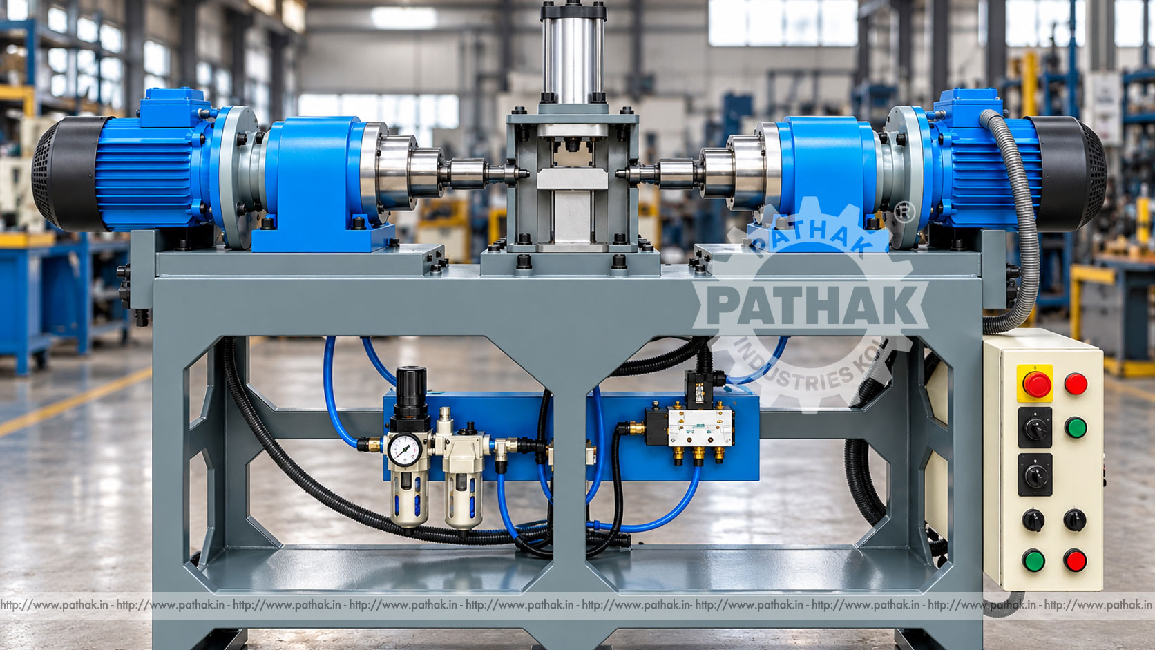
Riveting creates a permanent mechanical joint by deforming a rivet so that it securely captures the assembled components. In repeat manufacturing, joint quality depends on alignment, support, tooling shape, force, stroke, and cycle consistency. A Double Head Riveting Machine organises related riveting operations from opposing sides of the setup, helping manufacturers produce balanced and repeatable joints on suitable components.
Pathak Industries lists five configurations: Model-003, Model-005, Model-008, Model-012, and hydraulic Model-016-H. Their stated riveting capacities for mild steel rated at 38 kg/mm² ultimate tensile strength range from 3 to 16 mm. Depending on model, throat depth ranges from 110 to 225 mm, maximum shut height from 180 to 280 mm, and adjustable stroke from 0–30 or 0–45 mm.
A double head riveting machine uses two working heads arranged to approach associated rivet positions or sides of an assembly. The exact tooling and sequence depend on the component. Compared with handling two related joints through unrelated setups, the paired arrangement can improve alignment and reduce repeated repositioning.
The machine supports the work while controlled pressure forms the rivet head. A successful joint requires the correct rivet material and diameter, accurate hole preparation, proper grip length, matched dies, rigid support, and a force/stroke setting appropriate to the assembly.
Prepared components are located in a fixture, and the rivets are inserted or fed according to the production method. The operator verifies that the parts sit against their datums and that both forming tools align with the rivets. Initiating the approved cycle brings the heads into controlled engagement.
The tools upset the rivet material to create the required formed head. They then return so the completed assembly can be removed. Cycle timing is listed as adjustable from 0 to 9.9 seconds across the model range, allowing the process to be tuned for the confirmed rivet, material, and joint without assuming that one time suits every product.
Capacity is based on the material condition stated in the product table. A rivet made from a different alloy or strength can require different forming force. Selection should therefore use the real rivet drawing and material certificate, not diameter alone.
Throat depth describes how far the joint can be positioned from the accessible edge of the work. A shallow bracket may fit a 110 mm throat, while a wider panel or assembly may require the 200 or 225 mm reach of a larger model.
The nominal throat is not the only clearance to check. Fixtures, clamps, flanges, curved surfaces, and the second riveting head occupy space. A layout drawing should show the entire component in loading and riveting positions to confirm that nothing interferes.
Maximum shut height establishes the available vertical or tool-to-support envelope in the listed configuration. The workpiece, fixture, rivet projection, upper tool, lower support, and any wear allowance must fit within it. Model values range from 180 to 280 mm.
Stroke controls head travel. Models 003 and 005 list 0–30 mm, while the larger configurations list 0–45 mm. A properly set stroke allows safe approach and sufficient forming movement without unnecessary travel or over-compression.
Models 003, 005, 008, and 012 list an air-pressure range of 3–7 kg/cm². Their motors are respectively 0.25 HP (0.18 kW), 0.5 HP (0.37 kW), 1 HP (0.75 kW), and 1.5 HP (1.2 kW). The compressed-air supply must be clean, regulated, and capable of supporting the production cycle.
Model-016-H is the hydraulic configuration. It lists 0–80 kg/cm² hydraulic pressure and a 6 HP (4.5 kW) motor including the power pack. Hydraulic oil condition, temperature, filter state, hoses, seals, and pressure settings are central to consistent operation.
The forming tool controls the appearance and geometry of the finished rivet head. Tool faces should match the rivet type and desired profile. Misaligned, worn, cracked, or incorrectly sized tooling can produce an off-centre head, split material, marking, or incomplete fill.
Tools should be installed cleanly and secured at the specified position. Their relationship should be checked at low-risk setup conditions before a powered cycle. Tool changes require energy isolation and an approved setup procedure.
A fixture should establish repeatable datums, hold the assembly flat, and support the load around the rivet without obstructing the heads. Locating pins and stops must not distort the component or trap it after forming. If parts vary, the fixture needs enough control to prevent accumulated error at the second head.
Quick loading is useful only when it remains safe and accurate. Handles and clamps should stay outside the tool path. Sensors or interlocks may be considered where appropriate to the supplied configuration and risk assessment.
Double head riveting can support automotive components, brake or friction linings, cookware handles, sheet-metal assemblies, hinges, brackets, utensils, fabricated linkages, and repair work. It is particularly useful when paired rivets or related operations benefit from a common fixture.
Every application requires confirmation of rivet type, material stack, access, finished head, joint function, and required inspection. The machine creates a permanent joint, but the design engineer remains responsible for determining whether riveting is suitable for the service load.
Two heads can address related positions without transferring the assembly to a separate machine, depending on fixture and head layout.
Keeping the component in one fixture helps preserve the relationship between paired joints and other assembly features.
Adjustable stroke and timing allow an approved process to be documented and repeated for recurring work.
The 3–16 mm model range allows buyers to select a configuration appropriate to actual rivet strength, diameter, reach, and assembly envelope.
Visual inspection can identify tilted rivets, cracked heads, incomplete forming, excessive marking, gaps between layers, and component distortion. Dimensional checks may cover head diameter, height, concentricity, projection, or gap according to the drawing.
Critical applications may require push-out, torque, peel, shear, or other validated tests. Sampling frequency should reflect production risk and customer requirements. Results should be traceable to material, machine setting, tool set, fixture, operator, and batch.
Opposing heads create crushing and pinch hazards. Hands must remain outside the working zone, and guarding or an approved actuation arrangement must prevent access during movement. Operators should never hold a small loose component directly between forming tools.
Stored pneumatic or hydraulic energy must be released before maintenance. Leaks should never be checked by hand. Electrical isolation, supported moving members, verified zero energy, and restored guards are necessary before returning the machine to service.
Daily checks include tool condition, fixture security, fasteners, guards, air preparation, hoses, leakage, controls, and unusual sound or vibration. Clean debris from the work area without damaging sensors or pushing contamination into guides.
Planned service should cover alignment, bearings, slides, seals, valves, filters, lubrication, electrical connections, motor ventilation, and pressure verification. Hydraulic units also require oil-level and condition monitoring. Maintenance records help identify wear before joint quality changes.
Listed overall dimensions progress from 470 × 400 × 860 mm for Models 003 and 005 to 625 × 585 × 1325 mm for Model 012. Model 016-H is listed at 540 × 615 × 1375 mm. Additional space is needed for loading, guarding, utilities, maintenance, and material flow.
The machine should be installed level on a suitable floor. Air-powered versions require a compatible regulated supply, while the electrical service must match the confirmed motor and 415 V three-phase listing. Installation should be completed by qualified personnel.
Start with rivet material and diameter, joint stack, finished head, required force, component width, distance from edge to rivet, fixture height, batch size, and cycle target. Compare these values with capacity, throat depth, shut height, stroke, pressure, and overall size.
Choosing excessive capacity can increase cost and footprint without improving the joint; choosing too little can cause incomplete forming and overload. Pathak Industries can review actual samples or drawings and recommend a configuration, tooling, and fixture concept for the application.
The published mild-steel capacities are 3, 6, 8, 12, and 16 mm, based on the material strength stated in the product table.
Model-016-H lists the greatest throat depth at 225 mm, followed by Model-012 at 200 mm.
No. Models 003 through 012 list 3–7 kg/cm² air pressure, while Model-016-H is hydraulic and lists pressure up to 80 kg/cm².
Yes. All listed models specify adjustable cycle timing from 0 to 9.9 seconds.
Two heads can address related operations while the assembly remains located in a common setup, reducing repositioning when the application matches the arrangement.
Rivet material, hole preparation, grip length, tool shape, alignment, fixture support, stroke, pressure, time, and inspection all affect the finished joint.
Not automatically. A change in diameter, material, stack thickness, or head style requires process review and first-part validation.
Provide the assembly drawing or sample, rivet specification, joint positions, required strength, fixture envelope, batch quantity, utilities, and inspection criteria.
The Pathak Industries double head riveting range provides pneumatic and hydraulic choices for stated mild-steel rivet capacities from 3 to 16 mm. Selecting the correct throat, shut height, stroke, tooling, pressure system, and fixture allows the paired-head arrangement to deliver practical production benefits. Safe guarding, first-part approval, documented settings, joint inspection, and preventive maintenance remain essential to consistent permanent assemblies.