Head Office
117, Grand Trunk Road, Salkia Howrah-700013, Kolkata, India
 Hitesh PathakWed, Jun 22, 2022
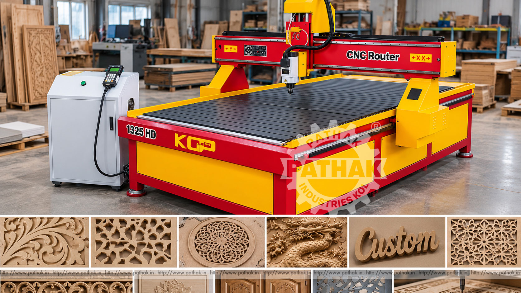
Signage, decorative panels, furniture details, and patterned woodwork often require clean geometry that would be slow to reproduce by hand. A CNC Wood Sinage Router moves a rotating cutter along programmed paths to create profiles, pockets, grooves, lettering, and engraved details. Although the product name uses “Sinage,” this guide uses the standard term “signage” when describing its applications.
The Pathak Industries CNC ROUTER DM1325 provides a listed 1300 × 2500 × 190 mm X-Y-Z working size, 190 mm feeding height, a 3 kW spindle, and a stated 6,000–24,000 rpm spindle range. Maximum movement is listed at 10,000 mm/min, while repeat positioning is specified below 0.05 mm per 300 mm. These figures make the machine relevant to full-panel woodworking and detailed routing when tooling, workholding, programming, and dust management are correctly planned.
A CNC router is a computer-controlled cutting machine with a high-speed rotating spindle. Digital instructions tell the axes where to position the cutter and how to follow the required geometry. Material remains secured on the table while the tool moves through controlled X, Y, and Z paths.
Unlike a handheld router, the CNC machine repeats coordinates from an approved program. It can produce lettering, logos, pockets, contours, reliefs, holes, and cut-outs. Consistency still depends on a correct drawing, suitable toolpath, sharp cutter, reliable workholding, and verified settings.
The workflow begins with artwork or a component drawing. Geometry is converted into toolpaths that define cutter movement, depth, direction, entry, exit, and cutting sequence. The resulting instructions are transferred to the machine in a supported format.
The operator fixes the panel to the aluminium platform, installs the selected cutter, and establishes work and tool references. After checking clearances and proving the program safely, the spindle reaches the approved speed and the axes follow the programmed route. Chips and dust are removed throughout the operation by the planned extraction arrangement.
The stated work envelope is 1300 mm in X, 2500 mm in Y, and 190 mm in Z, with a listed feeding height of 190 mm. This area suits many standard sheet and panel jobs, but actual usable clearance depends on cutter length, holder, spoilboard, clamps, work thickness, and safe Z travel.
A panel fitting within the table dimensions may still require margin for edge profiling or hold-down devices. Buyers should compare the largest raw sheet and deepest feature—not only the finished part—with the complete setup envelope.
The DM1325 lists a 3 kW spindle and a 6,000–24,000 rpm range. Spindle speed should be selected together with cutter diameter, number of flutes, material, feed rate, and depth of cut. Running at maximum speed is not automatically the best choice.
Incorrect combinations can create burning, melting, torn edges, premature tool wear, or excessive cutting load. New materials and tools should be proven conservatively while observing chip formation, edge finish, spindle sound, and workholding stability.
The product page lists maximum moving speed at 10,000 mm/min and repeat positioning below 0.05 mm per 300 mm. Maximum movement describes axis travel capability rather than a universal cutting feed. Practical cutting speed depends on tool and material conditions.
Square linear guide rails support axis motion, while stepper motors provide the listed drive arrangement. Clean rails, correctly maintained transmission parts, sound electrical connections, and controlled acceleration help preserve repeatable movement.
The specification lists tool diameters of 3.175, 4, 6, and 12 mm. Small cutters support fine details and narrow lettering but are more sensitive to deflection and breakage. Larger tools remove material more quickly and may provide stronger edge cutting, but they cannot reproduce very small internal corners.
Cutter style must match the operation. Straight, spiral, V-profile, ball-nose, and other woodworking geometries serve different tasks. Only sizes and holders compatible with the confirmed spindle arrangement should be installed.
The DM1325 can support:
Suitability for wood, plastic, composite, stone, or another material must be verified against the cutter, spindle, dust or chip controls, workholding, and machine configuration. One set of parameters cannot safely cover every material.
Good routing begins with clean digital geometry. Duplicate lines, open contours, overlapping shapes, or incorrect scale can cause wasted motion or damaged work. The design should identify finished dimensions, depths, radii, edge allowances, and which regions remain attached during machining.
Toolpaths should separate roughing, finishing, engraving, drilling, and profile cutting where appropriate. Tabs or an adequate holding method keep cut-out pieces from moving. A simulation or preview helps identify collisions, missed regions, and unintended depth changes before material is loaded.
The published data lists HPGL and G-code engraving instructions. File creation and transfer must follow the controller documentation supplied with the machine. Operators should verify units, origin, axis orientation, safe height, tool number, and program revision.
Approved programs should be stored with clear part names and version control. Changing a cutter, sheet thickness, zero point, or fixture can invalidate a previously proven cycle, so setup details should accompany the file.
The DM1325 has a listed aluminium platform. The workpiece must remain flat and immobile under cutting force. Mechanical clamps, fixtures, screws in permitted sacrificial areas, or another approved method may be used according to the job and supplied table arrangement.
Clamps must sit outside the cutter path and below safe clearance. Thin or bowed sheets may require additional support. A spoilboard can protect the platform during through-cutting and provide a replaceable reference surface.
The machine uses steel cross beams and has a listed overall size of 3000 × 1700 × 1900 mm and weight of approximately 1200 kg. The installation floor must support the load and keep the frame stable and level.
Additional space is needed for loading full panels, the control cabinet, dust collection, electrical access, tool storage, operator movement, and maintenance. The stated supply is AC 220 V/50 Hz, with a 380 V option noted; the actual delivered electrical configuration must be confirmed before installation.
Routing wood creates fine airborne dust and larger chips. An appropriate extraction system should capture material close to the cutter while allowing safe axis movement. The processed wood or sheet composition determines the required filtration, housekeeping, and personal protection.
Dust must not accumulate on rails, screws, motor ventilation, control cabinets, or around ignition sources. Cleaning should use approved methods rather than blowing contamination into bearings or electrical equipment.
Inspection can include overall size, pocket depth, groove width, hole position, letter shape, edge quality, relief detail, and surface condition. A first-piece record should capture tool, program revision, material batch, zero reference, and key settings.
Burning may indicate an unsuitable feed-speed relationship or blunt cutter. Fuzzy edges can relate to grain direction, tool geometry, or cutting direction. Dimensional drift can point to loose workholding, tool wear, lost motion, or reference error.
Approved programs allow the same lettering and profiles to be reproduced for repeat orders.
The 1300 × 2500 mm X-Y range supports many full-sheet signage and furniture-panel tasks.
Engraving, pocketing, grooving, profiling, and cut-outs can be organised in one setup when tooling and access permit.
Digital preparation makes it practical to produce custom names, patterns, and short-run designs without a dedicated physical template for every shape.
Daily checks include cutter and holder condition, table cleanliness, clamps, extraction, guide surfaces, cables, limit devices, guards, and emergency controls. Listen for unusual spindle, bearing, or axis noise and stop if movement becomes irregular.
Planned maintenance should follow the supplied schedule for lubrication, transmission adjustment, fasteners, electrical connections, cooling or ventilation, spindle condition, axis alignment, and reference accuracy. Energy must be isolated before servicing.
Provide sample designs or drawings, raw sheet dimensions, material types, maximum thickness, smallest detail, deepest cut, edge-finish requirement, batch sizes, and production target. Confirm that the 1300 × 2500 × 190 mm envelope, 3 kW spindle, tool range, controller, and workholding suit those jobs.
Also review extraction, electrical supply, software workflow, operator training, floor space, tooling, spare parts, loading access, and service support. Pathak Industries can evaluate the application against the DM1325 configuration without relying only on a general “CNC router” label.
The product page lists 1300 × 2500 × 190 mm for X, Y, and Z, with a 190 mm feeding height.
The listed spindle is 3 kW with a published range of 6,000–24,000 rpm.
The source lists 3.175, 4, 6, and 12 mm tool diameters. Exact holder compatibility should be confirmed.
Yes. Programmed engraving, pocketing, and profile routing make signage and lettering representative applications.
The listed repeat-positioning accuracy is below 0.05 mm per 300 mm under the specified machine conditions.
The product page mentions additional materials, but every application must be confirmed for cutter, spindle, workholding, chip control, and operating parameters.
Published overall dimensions are 3000 × 1700 × 1900 mm, with an approximate weight of 1200 kg.
Provide drawings, material, sheet size, thickness, details, cut depths, finish, batch quantity, utilities, extraction plan, and expected production rate.
The Pathak Industries DM1325 CNC wood signage router combines a full-panel working area, 3 kW high-speed spindle, programmed axis movement, and repeat positioning for suitable engraving and cutting work. Productive use depends on clean digital files, appropriate cutters, secure panels, controlled parameters, effective dust extraction, inspection, and disciplined maintenance.