Head Office
117, Grand Trunk Road, Salkia Howrah-700013, Kolkata, India
 Hitesh PathakTue, Jul 22, 2025
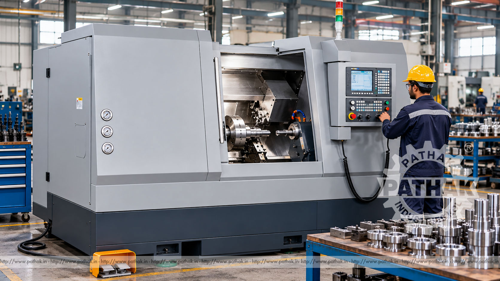
Many rotational components require more than external turning and boring. Flats, cross holes, slots, bolt circles, keyways, and off-centre features may otherwise send the part through several machines and setups. A CNC Turn Mill combines conventional lathe-axis machining with a powered turret that can drive suitable tools, allowing selected turning and milling operations to be organised in one CNC cycle.
The Pathak Industries TLPCTM-50A has an 8-inch hydraulic chuck, 500 mm swing over the bed, 400 mm maximum turning diameter, and 450 mm maximum workpiece length. Its spindle provides a 65 mm bore, 50 mm maximum through hole, A2-6 nose, 50–3000 r/min speed range, 117 Nm listed maximum torque, and an 11 kW motor. A BMT45 12-position power turret supports the combined process, while a hydraulic tailstock provides support for suitable shaft work.
A turn-mill machine begins with the architecture of a CNC lathe: a spindle holds and rotates the workpiece while controlled axes position cutting tools. Its powered turret adds live-tool capability, so selected tools can rotate independently of the main spindle. Coordinated spindle orientation and axis movement allow features to be machined away from the central turning axis.
This combination can reduce transfers between a lathe, drilling machine, and milling machine. Fewer setups may improve datum continuity and lower handling time. The practical advantage depends on the component geometry, available live-tool holders, spindle control, program, and whether every required feature lies within the confirmed machine configuration.
The workpiece is held in the hydraulic chuck or introduced through the spindle bore when compatible bar work is planned. Turning tools in the turret perform facing, outside turning, grooving, threading, or boring as required. The work rotates against stationary cutting edges during these operations.
For milling or off-axis drilling, the main spindle is positioned or controlled according to the operation while a powered turret station drives the selected cutter. The CNC coordinates tool movement and work orientation. After all accessible features are complete, the part is inspected or transferred if another setup is still needed.
The machine lists 500 mm maximum swing over the bed, 280 mm swing over the slide, 400 mm maximum turning diameter, and 450 mm maximum workpiece length. These figures describe different clearances. A component that fits the bed swing may still exceed turning diameter or interfere with the slide, turret, chuck jaws, toolholder, or enclosure.
Selection should use a setup drawing containing the raw stock, finished shape, jaw projection, tailstock support, longest tool, and required approach. The nominal maximum is not always the most practical size for a complex cycle with multiple live-tool stations.
The specified 8-inch hydraulic chuck supports repeatable opening and closing in production. Jaw choice and clamping pressure must suit the part. Excessive force can distort thin components, while insufficient force can allow movement under turning or interrupted milling loads.
Soft jaws can be machined to support a specific diameter and locate an axial face. Hard jaws may suit appropriate raw stock and recurring general work. Jaw engagement, grip length, centrifugal effects, cutter forces, and part projection should all be considered. A program should never be proven with uncertain clamping.
The spindle bore is listed at 65 mm, with a 50 mm maximum through hole. Through-hole capacity is the relevant published limit for stock intended to pass through the spindle arrangement. The bar or tube must also be straight, suitable for rotation, and supported by an approved feeding or stock-support system.
Long unsupported material projecting behind the spindle can whip violently. Any bar-feed or support arrangement needs guarding and capacity suited to stock diameter, length, speed, and mass. Do not infer that every 50 mm workpiece can safely rotate at maximum spindle speed.
The TLPCTM-50A offers 50–3000 r/min, with listed maximum spindle output torque of 117 Nm and an 11 kW motor. Lower speeds and useful torque support selected larger-diameter or heavier cutting operations, while higher speed may suit compatible smaller diameters and tools.
Correct cutting conditions depend on material, diameter, insert or cutter, engagement, coolant, rigidity, and finish. Maximum torque and maximum speed do not necessarily occur at the same operating point. Process planning should use the spindle’s actual power/torque characteristics where demanding cuts are proposed.
The machine has a BMT45 12-position power turret. BMT-style mounting provides a defined interface for turning holders and compatible driven-tool units. Twelve stations allow a combination of outside tools, boring tools, drills, mills, and other process tooling, subject to adjacent-station clearance.
Published square tool shank size is 25 × 25 mm. Boring tool shank options are listed at 40, 30, 25, and 20 mm. Live-tool specifications such as speed, torque, collet range, and orientation should be confirmed for the supplied holders because they are not stated in the product record.
Suitable programmed cycles may include facing, straight turning, step turning, taper generation, grooving, part preparation, threading, drilling on centre, and boring. The exact list depends on tools, control functions, component material, and setup. A stable workpiece and properly set tool centre height are essential.
Roughing should leave controlled stock for finishing while managing chip shape and heat. Finishing operations need tools and cutting conditions appropriate to tolerance and surface requirements. Tool offsets should be maintained through an authorised wear-control method rather than informal program edits.
Driven tools can support selected flats, slots, radial holes, axial bolt patterns, keyways, and similar features. The main spindle must orient or index the work accurately for these operations. Feature geometry, live-tool capacity, axis availability, and holder clearance determine what is practical.
Milling on a turn-mill machine involves a different rigidity and engagement pattern from a large machining centre. Cutter diameter, overhang, depth, and toolpath should reflect the live tooling and workholding. Heavy cuts should not be assumed merely because the main spindle has adequate turning power.
The hydraulic tailstock has 450 mm published travel and an MT5 quill taper. It can support suitable shaft components with a compatible centre, reducing deflection and vibration caused by workpiece projection. Tailstock force and position must suit the work without distorting it.
Centre holes should be correctly prepared and clean. The centre and taper need inspection for damage, lubrication, and seating. Tailstock use must also be considered when programming turret movement so tools and holders cannot collide with the support assembly.
The product table lists maximum loading of 200 kg for disc parts and 500 kg for shaft parts. These limits require interpretation with workholding, balance, projection, speed, tailstock support, and chuck capacity. Weight alone does not prove that a component is safe to rotate.
Heavy components need an engineered loading method, such as a suitable crane or lifting device, and approved attachment points. The operator should not guide a suspended load with hands placed between the part and chuck. A slow, controlled setup and balance review are essential before running.
The product data lists 200 mm X-axis travel and 18 m/min rapid traverse for both X and Z. Another imported travel row is inconsistently labelled, so longitudinal working travel should be confirmed from the final technical sheet. Rapid rates describe non-cutting movement, not the feed for machining.
Cycle efficiency comes from safe approach points, short but collision-free moves, logical tool order, controlled spindle changes, and reduced handling. Very small reductions in rapid distance may be less valuable than robust chip clearance and easy program proving.
CNC turn mills can support production workshops, component manufacturers, toolrooms, maintenance departments, and engineering plants. Typical parts include flanges, bushes, couplings, hubs, pins, shafts, valve components, rollers, and rotational parts containing cross holes, flats, slots, or bolt patterns.
The machine is particularly useful when turned and milled features share a common datum. Completing them in one clamping can reduce intermediate inspection and workholding. Parts that need extensive work on both ends may still require a second operation or additional equipment, depending on the supplied configuration.
A turn-mill program must coordinate turret index, tool offsets, chuck and jaw geometry, spindle state, live-tool commands, tailstock, coolant, and axis positions. Simulation is valuable, but the physical setup must match its digital representation. Toolholder bodies and unused adjacent tools can create collision risks even when the cutter path is correct.
New cycles should be proven under controlled conditions with verified offsets and reduced motion where appropriate. Safe retract points, spindle orientation, and turret indexing clearance need special attention. Program revisions should be recorded so an earlier unverified file cannot return to production.
Turning and milling features often have geometric relationships such as concentricity, position, runout, or angular spacing. Keeping the part in one setup can support these relationships, but results still depend on machine condition, chucking, tools, thermal stability, program, and measurement.
The first completed part should be checked against the drawing before batch production. Measure both individual dimensions and the relationships between turned and milled features. Tool wear and insert changes should be managed through documented offsets and periodic inspection.
Turning can create long stringy chips, while milling and drilling may produce shorter chips in different directions. Tool geometry and cutting conditions should promote manageable chip formation. Chips must not wrap around the work, accumulate near the chuck, or interfere with live tools and turret indexing.
Coolant selection and delivery should suit materials and operations. Concentration, filtration, level, and cleanliness need monitoring. Chips should be removed with appropriate tools after the machine reaches a safe state, never by hand during rotation.
Published overall dimensions are 2700 × 1890 × 1945 mm. Installation planning should add space for doors, bar support, chip removal, coolant service, electrical cabinets, tool setup, material loading, and maintenance. Foundation and lifting requirements need confirmation from the final drawings.
The enclosure and interlocks protect workers from rotating components, tools, chips, coolant, and automatic movement. They must remain operational. Chuck keys or setup tools must be removed, and clamping confirmed before spindle start. Maintenance, jaw work, tool changes, or entry into hazardous areas requires the authorised safe state and energy isolation.
Daily checks should include chuck pressure and lubrication, jaws, spindle, turret, driven-tool holders, tailstock, coolant, lubrication system, guards, interlocks, and chip buildup. Unusual vibration, heat, noise, tool-change behaviour, or hydraulic leakage should be investigated promptly.
Scheduled maintenance covers spindle and turret alignment, chuck service, hydraulic oil and filters, axis lubrication, tailstock, electrical systems, coolant equipment, and geometric checks. Control and program backups should form part of the maintenance plan.
Start with representative drawings. Record raw-stock diameter and length, finished turning diameter, through-bar needs, component mass, milled features, hole orientations, tolerances, surface finish, materials, and batch sizes. Identify which operations can genuinely be completed in one clamping.
Confirm spindle capacity, chuck, torque, power turret and live-tool specifications, tailstock, axis travels, control functions, toolholders, loading, bar support, and installation. Pathak Industries can assess the TLPCTM-50A against these components. Any required live-tool speed, torque, or axis function should be documented in the final offer.
It combines CNC turning with powered-tool operations so selected milled, drilled, and off-centre features can be produced in the same workholding setup.
The TLPCTM-50A lists 400 mm maximum turning diameter, with 500 mm swing over the bed and 280 mm over the slide.
The spindle has a 65 mm bore and a listed maximum through hole of 50 mm. Stock support and safe speed still require evaluation.
The published range is 50–3000 r/min, powered by an 11 kW spindle motor.
The machine lists a BMT45 12-position power turret for compatible turning and driven-tool holders.
It supports suitable shaft work, helping control deflection and vibration. The tailstock lists 450 mm travel and an MT5 taper.
No. Capability depends on axis functions, live-tool speed and torque, holders, clearance, workholding, and component geometry.
Provide drawings, stock sizes, part weights, materials, tolerances, turning and milling features, batch sizes, tooling needs, bar support, utilities, and installation constraints.
The strongest reason to use a CNC turn mill is not simply that it has powered tools. Its value comes from completing compatible turning and milling features while the component remains referenced in one controlled setup. Thoughtful workholding, tooling, programming, proving, inspection, and maintenance are essential to realise that benefit.
Review the TLPCTM-50A data on the CNC Turn Mill product page and share representative drawings with Pathak Industries. Confirm axis configuration, live-tool capability, holders, chuck, tailstock, control functions, loading, installation, and acceptance criteria before ordering.