Head Office
117, Grand Trunk Road, Salkia Howrah-700013, Kolkata, India
 Hitesh PathakThu, Dec 30, 2021
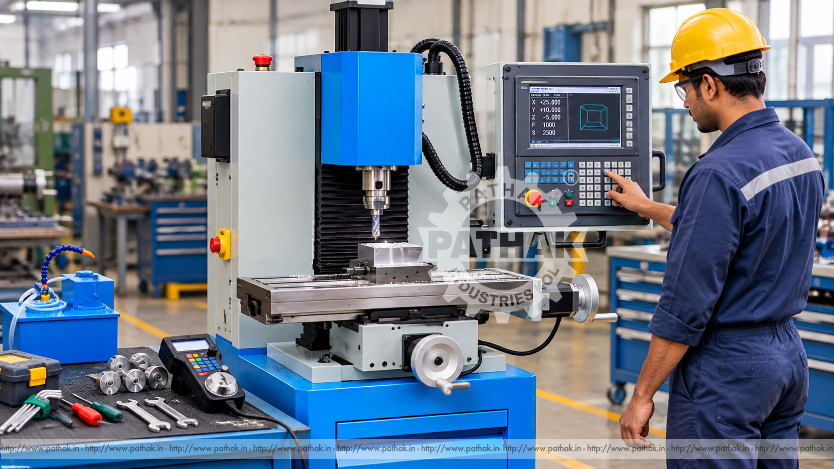
Learning CNC machining requires more than memorising codes. Students and new operators need to connect a drawing with coordinates, tooling, work offsets, cutting parameters, machine movement, inspection, and safe shop practice. A CNC Trainer Milling Machine provides a compact platform for developing those skills through supervised, hands-on machining.
Trainer machines are suited to technical institutes, engineering colleges, skill-development centres, tool rooms, and industrial training departments. They allow learners to progress from basic axis movement and program entry to complete milling cycles while working on equipment that reflects the operating principles of larger CNC machining centres.
A CNC trainer milling machine is a computer-controlled machine tool designed for education, demonstration, prototype work, and suitable light machining. Its controller interprets a part program and commands the machine axes and spindle to move a cutting tool relative to a securely clamped workpiece.
The training format normally provides a manageable work envelope, accessible controls, and clear visibility of the machining area. It teaches the same foundation used on industrial CNC mills: machine coordinates, work coordinates, tool offsets, spindle commands, feed commands, interpolation, program verification, and dimensional inspection.
In a typical vertical arrangement, the spindle rotates an end mill, drill, face mill, or other compatible cutter. The table and spindle assembly move along controlled axes. X usually represents left-to-right table movement, Y represents front-to-back movement, and Z represents vertical tool movement. Direction conventions must always be confirmed on the actual control.
The controller follows programmed blocks containing preparatory functions, coordinates, feeds, spindle speeds, tool data, and auxiliary commands. Axis drives convert those instructions into precise movement. Feedback and control systems help the axes reach commanded positions within the machine's designed capability.
Features vary by configuration. Buyers should confirm axis travels, table capacity, spindle taper, speed range, motor ratings, controller type, programming functions, tooling, enclosure, and power requirements from the current technical offer.
A structured CNC milling course can use the trainer to teach:
Training should begin with the engineering drawing. Learners identify datums, dimensions, tolerances, hole locations, profiles, and surface requirements. They then plan stock size, setup orientation, workholding, tools, operation order, inspection stages, and a safe tool path.
The program translates this process plan into coordinates and commands. Before cutting, the learner should verify syntax, tool numbers, offsets, spindle direction, clearance planes, approach moves, feeds, and speeds. A controlled program prove-out connects classroom programming with real machine behaviour.
Machine coordinates are based on the machine's fixed reference system. Work coordinates allow the programmer to define a convenient datum on the component or fixture. Tool offsets account for differences in tool length and, where applicable, cutter radius.
Incorrect work or tool offsets are among the most serious setup errors because an otherwise correct program can move to the wrong physical location. Training should require learners to identify the active coordinate system, verify each offset, and compare displayed positions with the actual setup before cycle start.
A CNC program is arranged in blocks. Depending on the supplied controller, blocks may define rapid positioning, feed movement, linear or circular interpolation, plane selection, units, spindle operation, tool changes, coordinate systems, canned cycles, and program end.
Students should learn modal behaviour: some commands remain active until cancelled or replaced. They should also understand safe-start blocks, return and clearance positions, program numbering, comments, and the difference between commanded feed and rapid movement.
Controller syntax differs. Programs must be written and verified for the exact control and machine configuration rather than copied blindly from another machine.
A progressive course may include:
Exercises should increase in complexity only after the learner demonstrates safe control of the previous stage.
Common training tools include centre drills or spot drills, twist drills, end mills, slot drills, face mills, chamfer tools, and boring tools compatible with the machine. Tool holders and collets must match the spindle system and be clean, undamaged, and correctly tightened.
Tool selection depends on the material, feature geometry, required finish, spindle capability, and rigidity. Short tool projection improves stability. Tool numbers and physical magazine or holder positions must match the program and offset table.
A milling vice is convenient for regular blocks, while step clamps, angle plates, fixture plates, soft jaws, and purpose-built fixtures support other geometries. The work must resist cutting forces without distortion or movement.
Clean the table, vice, parallels, and component before clamping. A small chip beneath a reference surface can create a measurable error. Check that clamps, jaws, and fixtures remain outside every programmed tool path and spindle-body clearance envelope.
Spindle speed relates to cutting speed and tool diameter. Feed depends on cutter type, tooth count, recommended chip load, material, and machine condition. Depth and width of cut must remain within the rigidity and power of the training machine.
Use tool-manufacturer guidance as a starting point, adjusted for the machine and setup. Excessive parameters can cause chatter, tool breakage, work movement, poor finish, and overload. Parameters that are too conservative may rub the tool rather than cut effectively.
No new or edited program should begin with an unattended full-speed cycle. Review the code, compare tools with the tool table, verify offsets, and confirm the workholding. Use simulation or graphics if supported, but do not treat screen verification as proof of physical clearance.
Prove the program using the machine's approved methods, such as single-block operation, reduced rapid override, controlled feed override, dry run, and a safe Z clearance. Keep one hand ready to stop motion while remaining outside the hazard area. Once the first part is verified, restore production settings deliberately.
Inspection completes the learning cycle. Students should use callipers, micrometers, depth instruments, height gauges, indicators, bore gauges, and other suitable equipment according to the drawing tolerance.
When a dimension differs from target, investigate the cause before changing an offset. Possible causes include incorrect datum setting, tool wear, work movement, thermal effects, backlash, programming errors, or measuring technique. Offset correction should be documented and applied in the correct direction.
In addition to structured education, a CNC trainer mill can support suitable prototype parts, laboratory fixtures, demonstration components, maintenance items, student projects, and low-volume work. Typical features include faces, slots, pockets, profiles, hole patterns, counterbores, and chamfers.
Commercial suitability depends on the required envelope, material-removal rate, tolerance, finish, tooling, duty cycle, and output. A trainer should not automatically be treated as a substitute for a high-power production machining centre.
CNC control does not remove machining hazards. The machine can execute an incorrect command rapidly and repeatably. Training must therefore combine programming with risk awareness and supervised operating discipline.
The machine requires a level, load-rated foundation with access for installation, operation, cleaning, and service. Electrical supply, earthing, protection, and isolation must match the machine and local standards. Provide suitable lighting, ventilation, chip handling, coolant management, and fire precautions.
A teaching layout should give the instructor clear visibility without placing observers inside the operating zone. Mark safe standing areas, control access, display emergency procedures, and provide secure storage for tools and measuring equipment.
Daily checks should cover lubrication, coolant where fitted, tool holders, worktable condition, guards, interlocks, controls, air supply if applicable, and unusual noise or movement. Clean chips without damaging guideway covers, seals, or electrical equipment.
Planned service may include lubrication-system inspection, axis-gib or guide checks, drive components, spindle condition, electrical connections, filters, coolant condition, backlash assessment, and machine alignment. Follow the manufacturer's schedule and keep maintenance and accuracy records.
Start with the curriculum and representative parts. Compare:
Pathak Industries can review training goals, sample components, available space, utilities, and controller preferences against the current machine configuration.
It is suited to supervised students, apprentices, instructors, programmers, operators in conversion training, prototype teams, and maintenance personnel who need practical CNC milling experience.
CNC trainer mills commonly use controller-specific G- and M-code conventions. Exact syntax and available functions depend on the supplied control and should be confirmed from its documentation.
Where supported, learners can practise manual jogging, MDI commands, program editing, automatic cycles, single-block execution, and feed or rapid overrides.
Yes, it can machine suitable components within its work envelope, spindle capability, tooling, accuracy, and duty rating. The full setup must be checked before machining.
Work offsets connect program coordinates to the component datum, while tool offsets account for tool geometry. Incorrect values can cause dimensional errors or collisions.
No. Simulation helps find programming problems, but physical workholding, tool projection, offsets, and machine clearances must also be verified through an approved prove-out procedure.
Requirements depend on the curriculum, but often include compatible holders and collets, end mills, drills, a vice or clamp set, edge or datum-setting equipment, and measuring instruments.
Provide the intended syllabus, learner level, controller preference, sample drawings, materials, required travels and tooling, available utilities, safety requirements, and expected daily use.
A CNC Trainer Milling Machine turns programming theory into practical manufacturing knowledge. It helps learners understand coordinates, offsets, tooling, workholding, cutting data, program verification, inspection, and safe machine operation on one integrated platform.
The right trainer should fit the curriculum as well as the parts. Controller relevance, travel, spindle capability, guarding, laboratory layout, tooling, documentation, instructor support, and maintenance all influence long-term training value. Confirm the current technical specification and educational objectives before selecting a configuration.