Head Office
117, Grand Trunk Road, Salkia Howrah-700013, Kolkata, India
 Hitesh PathakTue, Jun 23, 2026
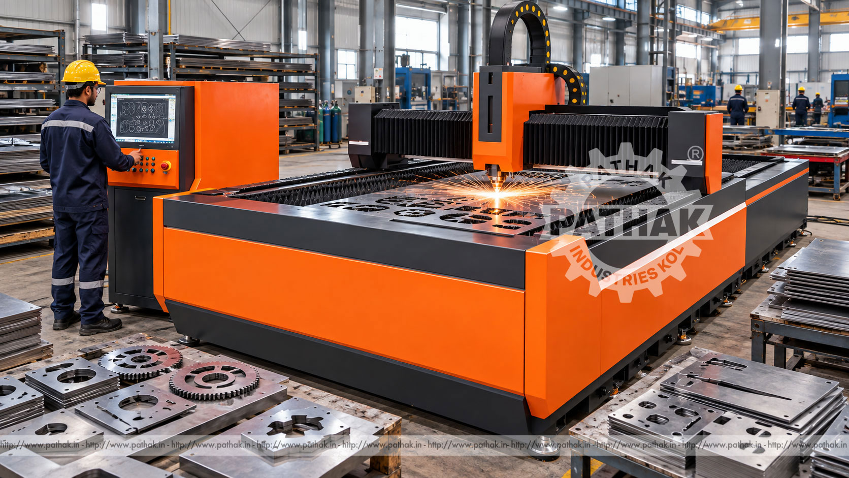
Sheet-metal production often requires profiles, holes, slots, and contours that would be slow to prepare with several separate mechanical operations. A CNC Fiber Laser Cutting Machine uses a focused beam and programmed axis movement to cut compatible metal sheet without a conventional toothed tool contacting the work. This supports precise contouring, narrow cutting paths, and efficient nesting of multiple components on one sheet.
The Pathak Industries product record describes a 1000 W laser system with a maximum working area of 3000 × 1500 mm, defined as 1500 mm X travel and 3000 mm Y travel, plus 120 mm Z working movement. Published cutting guidance distinguishes between “best” and maximum thickness for carbon steel, stainless steel, aluminium, and copper. These figures are useful selection references, but real results also depend on material grade and surface, assist gas, focus, nozzle, speed, pierce method, and required edge quality.
A fiber laser cutting machine generates laser energy and delivers it through an optical path to a cutting head. A focusing assembly concentrates the beam into a small spot on the sheet. The energy heats the material locally, while assist gas helps remove molten metal from the kerf and supports the selected cutting process.
CNC motion guides the cutting head along programmed contours. Because there is no mechanical cutting edge pushing through the sheet, the machine can create complex two-dimensional profiles without changing a punch or blade for each shape. The process still requires careful programming, stable material support, correct utilities, and trained operation.
The job begins with an approved drawing or CAD profile. Programming software converts the geometry into toolpaths, adds lead-ins and lead-outs, establishes pierce points, assigns process conditions, and nests parts within the sheet. The operator checks material identity, thickness, sheet size, and program revision before loading.
The sheet is placed on the cutting bed and referenced. After utilities and safety systems are verified, the head moves to the first pierce point. The beam penetrates the material, then follows the programmed path while height control maintains the required relationship between nozzle and surface. Finished parts and skeleton material are removed after the cycle reaches a safe state.
The stored specification lists 1000 W laser power. Power influences the process window, but it does not define cut capability alone. Material absorption, conductivity, thickness, assist gas, optical condition, focus, nozzle, and travel speed all interact with the beam.
Maximum thickness describes an upper published cutting limit under suitable conditions and may not provide the same speed or edge quality as the best-cutting range. Buyers should distinguish occasional maximum capability from the thicknesses processed every day. Production selection should be based on the dominant material mix and quality requirement.
For the 1000 W configuration, the product table lists 8 mm as the best cutting thickness for carbon steel and 10 mm as the maximum. Carbon steel cutting commonly uses a process selected around material thickness and desired edge condition, with assist gas parameters developed accordingly.
Scale, rust, protective coatings, inconsistent thickness, and warped sheets can affect piercing and height control. Material should be suitable for laser processing and supported so it remains stable across the bed. A trial and inspection plan is advisable when a new grade or supplier is introduced.
The stored data lists 5 mm as the best thickness for stainless steel and 6 mm as the maximum. Stainless work often requires attention to edge colour, oxidation, burr, and downstream finishing. Assist-gas quality and pressure can materially affect the result.
Sheet surface should be clean, and any protective film must be confirmed suitable for the cutting process. Cut parameters should reflect the actual alloy and finish. Do not assume that every stainless grade behaves identically at the same nominal thickness.
For both aluminium and copper, the product record lists 2 mm as the best cutting thickness and 3 mm as the maximum. These conductive and reflective materials present different process behaviour from carbon steel. Correct machine configuration, process development, and material confirmation are essential.
Operators should follow the approved settings and never experiment outside the supported material range without technical review. Surface condition and alloy can change cutting response. Finished components should be inspected for burr, dross, edge condition, and dimensional result before a batch is released.
The maximum published work area is 3000 × 1500 mm. This accommodates commonly used sheet formats within the stated envelope, but the usable cutting region and loading clearance should be confirmed from the final machine drawing. Sheet overhang, poor support, or collision with clamps and bed components must be avoided.
Nesting software arranges parts to improve material utilisation while leaving appropriate spacing for heat, kerf, lead-ins, and stable remnants. Good nesting balances yield with reliable cutting. Placing parts too close together can create thermal distortion, unstable small webs, or difficulty removing finished pieces.
The listed Z working movement is 120 mm. Vertical motion allows the head to approach, pierce, cut, retract, and accommodate the configured sheet position. During cutting, height control helps maintain the required nozzle stand-off as the head moves across the surface.
Warped sheets, raised cut parts, slag buildup, or unsuitable remnants can create collision risk. The cutting bed should be maintained, and programs should include safe movement. A functioning height-sensing system does not remove the need for flat material and good process planning.
Assist gas clears molten material from the kerf and influences chemical reaction, edge appearance, cutting speed, and dross. The correct gas depends on material and desired result. Gas supply must provide the purity, pressure, and flow required by the approved process.
Pipes, regulators, filters, valves, and connections should be rated and kept clean. Leaks waste gas and can destabilise the process. Cylinders or bulk systems need secure installation and handling under the site’s gas-safety procedure.
Clean geometry reduces unnecessary moves and repeated contours. The programmer should remove duplicates, close profiles correctly, assign cut order, and decide whether internal features are completed before external outlines. Small parts may need strategies that prevent tipping or movement after separation.
Pierce location should avoid damage to finished edges, while lead geometry should suit thickness and contour. Heat should be distributed across the sheet rather than concentrated in one small region. Program simulation helps identify path issues, but the operator must still verify the real bed, material, and machine state.
The focused beam creates a narrow path called the kerf. Programming compensation accounts for its width so the finished contour aligns with the drawing. Kerf can vary with material, power, focus, nozzle, gas, and speed, so validated values should be used for each process.
Dimensional outcome also depends on thermal expansion, sheet movement, calibration, and measurement method. Edge inspection should consider dross, taper, striations, heat effect, and corner quality. Machine positioning capability alone does not guarantee every finished-part tolerance.
CNC fiber laser machines support precision fabrication, enclosure manufacturing, control-panel production, sheet-metal components, brackets, covers, signs, machine guards, furniture parts, duct components, and general engineering work. They are useful where part geometry changes frequently or multiple shapes need to be nested on one sheet.
The machine may operate as the first step before bending, welding, machining, coating, or assembly. Downstream needs should influence cut strategy. For example, a bend line near a cut edge, a weld-preparation requirement, or a cosmetic face can change acceptable edge condition and part orientation.
The product record lists an automatic lubrication system. It helps deliver lubricant to specified motion components at controlled intervals, reducing dependence on manual application. The reservoir level, lines, distribution points, and alarms still require inspection.
Automatic lubrication should not be mistaken for maintenance-free operation. Rails, drives, bellows, cable carriers, and the cutting area must be kept within the cleanliness requirements. Metal dust and slag should not be allowed to accumulate around motion components.
A chiller is included in the stored configuration, supporting temperature control for the laser system. Cooling-fluid quality, level, cleanliness, ambient limits, and maintenance need to follow the supplied instructions. Temperature instability can affect reliability and process consistency.
The installation environment should control dust, moisture, and excessive heat. Electrical cabinets, optical components, and cooling equipment need service clearance and clean airflow. Facility planning should also address fume extraction and collected particulate from the cutting process.
Fiber laser radiation can cause severe eye and skin injury, including from reflected energy. Enclosures, interlocks, viewing systems, warning devices, and access controls must remain functional. Operators and maintenance personnel require training appropriate to their role and the supplied laser classification.
Cutting also creates hot parts, sparks, fumes, sharp edges, compressed-gas hazards, and fire risk. The cutting bed and extraction system should be cleaned at the prescribed intervals. Materials with unknown coatings or hazardous emissions should not be processed without assessment. Before service, isolate electrical, pneumatic, gas, laser, and other stored energy.
Daily checks should cover nozzle condition and centring, protective optical elements, focus system, cutting bed, extraction, chiller, lubrication, gas supply, alarms, and motion area. A contaminated nozzle or protective window can quickly reduce cut quality. Consumables should be replaced using clean handling procedures.
Scheduled work includes motion calibration, drive inspection, cooling service, extraction maintenance, electrical checks, gas-system leak testing, lubrication-system service, and optical-path care as specified. Cut-quality records can help identify gradual changes before they create a large quantity of nonconforming parts.
List the materials, grades, thickness distribution, sheet sizes, part tolerances, edge requirements, annual volume, and downstream operations. Separate common daily work from occasional maximum-thickness jobs. Estimate material utilisation and handling needs using representative nests.
Confirm laser power, work area, head configuration, supported gases, chiller, extraction, electrical load, software, controls, loading method, service support, and consumables. Pathak Industries can compare the 1000 W configuration with representative drawings. Every material-thickness combination should be confirmed in the final technical offer.
It uses a focused laser beam and programmed motion to cut compatible sheet metal profiles without a conventional mechanical cutting edge.
The matching maximum and axis data define a 3000 × 1500 mm working area, with 120 mm Z movement.
The product record lists a 1000 W laser configuration.
The table lists 8 mm as best cutting thickness and 10 mm as maximum for carbon steel under suitable conditions.
The published guidance shows 5 mm best and 6 mm maximum thickness for stainless steel.
The product table lists both materials at 2 mm best and 3 mm maximum thickness. Alloy, surface, gas, and process approval remain important.
It removes molten material from the kerf and influences cutting reaction, speed, dross, oxidation, and edge appearance.
Provide materials, grades, thicknesses, sheet size, drawings, tolerances, edge quality, production volume, utilities, gas preference, loading method, and installation space.
A 1000 W CNC fiber laser can support flexible sheet-metal production when power, material, gas, focus, motion, extraction, nesting, and inspection are developed as one process. Maximum thickness alone is not a sufficient buying criterion; common work and required edge quality should drive selection.
Review the published data on the CNC Fiber Laser Cutting product page and share representative drawings with Pathak Industries. Confirm working area, material capability, utilities, software, extraction, gas systems, loading, safety provisions, and acceptance criteria before ordering.