Head Office
117, Grand Trunk Road, Salkia Howrah-700013, Kolkata, India
 Hitesh PathakWed, Dec 28, 2022
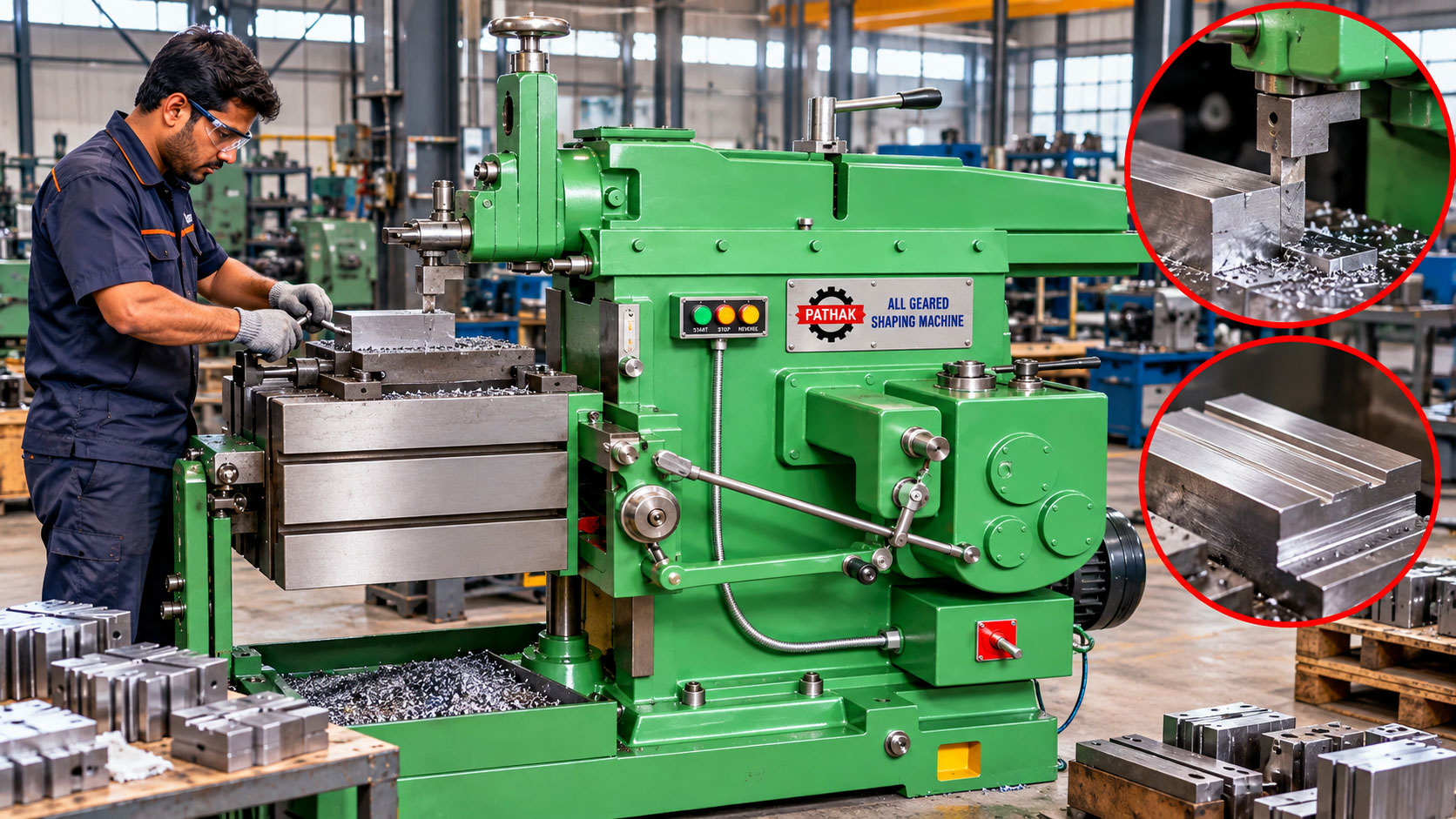
For blocks, repair components, dies, keys, slots, and small-to-medium fabrications, shaping remains a practical machining process. An All Geared Shaping Machine reciprocates a single-point cutting tool across securely clamped work. Adjustable ram travel positions the cutting stroke over the required area, while an all-geared drive provides selectable mechanical transmission for different jobs.
Pathak Industries lists six models—SS12, SS18, SS24, SS30, SS36, and SS40—with maximum working strokes from 14 to 42 inches. The range allows workshops to match the machine to component size, table travel, tool-slide movement, available power, and expected cutting duty. This guide explains the shaping process, machine features, applications, setup, tooling, safety, maintenance, and model-selection factors.
A shaping machine removes material through the linear reciprocating motion of a single-point tool. The tool normally cuts during the forward stroke and clears the work during the return stroke. After each cutting stroke, the table or tool receives a controlled feed so the next pass removes material beside the previous one.
The term “all geared” refers to a mechanical drive and speed-selection arrangement based on gears. Compared with changing belt positions for every operating condition, selectable gearing provides a structured way to set ram speed within the machine's available range. Correct selection still depends on work material, tool, stroke length, depth of cut, and machine model.
The workpiece is clamped in a vice, fixture, or directly on the table. The operator positions the job so the surface to be machined lies within table travel and below the ram. The tool is secured in the tool head, and ram stroke length and position are adjusted to cover the cutting area with safe approach and overtravel.
When the machine runs, the ram carries the tool across the work on the cutting stroke. The tool removes a chip, then returns to its starting position. A clapper arrangement allows suitable tools to lift or relieve during the return stroke, reducing rubbing against the newly cut surface.
Feed is applied between strokes. Repeated passes generate a flat, angled, vertical, or formed surface depending on tool orientation, table movement, and setup. Depth is introduced gradually through the tool slide or work positioning system until the required dimension is achieved.
The published series covers six machine sizes:
Working stroke is only one selection criterion. Table surface, horizontal travel, tool-slide travel, table-to-ram clearance, ram support, machine mass, and available power must also suit the job and fixture.
The stroke must cover the entire cutting length plus sufficient approach and clearance at both ends. Excessive stroke wastes cycle time and increases unnecessary ram travel, while insufficient stroke can leave an incomplete surface or cause the tool to reverse while engaged.
The listed range progresses from 14 inches on SS12 to 42 inches on SS40. Ram position should be adjusted so the cutting portion of the stroke lies correctly over the work. Before applying power, rotate or inch the mechanism according to the operating procedure to confirm that the tool, holder, ram, and clapper clear the work and fixture throughout the complete cycle.
The top clamping surface grows with model size, from a listed 14 × 11 inches on SS12 to 40 × 20.5 inches on SS40. Horizontal table traverse ranges from 16 to 36 inches. These values help establish whether a component and its fixture can be positioned for the intended cut.
Workholding must resist the intermittent cutting force without shifting. A machine vice is suitable for many blocks and repair parts, while irregular fabrications may require angle plates, clamps, stops, parallels, or a dedicated fixture. All supporting surfaces should be clean, and clamping force should be distributed so the work does not distort.
Clamps, bolts, and fixtures must remain outside the tool path. Long or tall work may need extra support, but supports must not restrict table feed or create collision points.
Published tool-slide traverse ranges from 5 inches on SS12 to 11 inches on SS40. The slide allows depth setting and supports machining at selected tool-head angles. This makes the shaper useful for horizontal surfaces, vertical faces, shoulders, angular features, and certain grooves.
Tool projection should be kept as short as practical. Excessive overhang encourages chatter and reduces rigidity. Tool-head angle, clapper orientation, and cutting direction must be arranged so the tool cuts securely and clears correctly on return.
Shapers typically use high-speed-steel or carbide-tipped single-point tools selected for the work material and operation. Straight tools can generate broad flat surfaces, side tools machine shoulders and vertical faces, and narrow tools produce slots or keyways. Form tools may create specific profiles when cutting load and machine capacity allow.
Tool geometry includes rake, relief, cutting-edge angle, and nose radius. A sharp tool with suitable clearance lowers cutting force and improves finish. A damaged or poorly ground edge can rub, overheat, chatter, or push the work out of position.
Tool selection should consider material hardness, interrupted cuts, desired finish, depth, feed, and machine rigidity. Always follow approved cutting data and begin a new setup conservatively.
An appropriately configured shaping machine can perform:
The process is especially useful where simple tooling, clear visibility, and flexible workholding are more important than high-volume automated production.
Many operations use tools that can be ground and maintained within a conventional workshop, reducing dependence on complex multi-edge cutters.
The geared drive provides defined speed options—three on SS12 and SS18, and four on SS24 through SS40—so operation can be matched to different stroke lengths and materials.
Vices, clamps, angle plates, and fixtures allow blocks, repair parts, and fabricated components to be arranged for different faces and features.
The open machining arrangement allows the operator to observe chip formation and surface progress from a safe position outside the moving zones.
Ram speed must suit the work material, tool, stroke length, and machine capacity. Longer strokes create different ram motion and cycle timing from short strokes. Select a conservative setting for a new job and observe chip formation, vibration, sound, and surface finish.
Feed determines the spacing between adjacent tool passes. A coarse feed can raise output but may leave pronounced feed marks and increase cutting load. A finer feed supports finishing but requires more strokes. Depth of cut should remain within the rigidity of the tool, workholding, and machine.
Roughing and finishing are often separated. Roughing passes remove the bulk of stock with an appropriate allowance left for one or more controlled finishing passes.
Finished accuracy depends on machine alignment, slide condition, ram support, table stability, tool geometry, clamping, cutting parameters, and measurement practice. A rigid setup is essential because the tool experiences an intermittent load on every cutting stroke.
Chatter may result from tool overhang, a loose workpiece, worn slides, excessive speed, unsuitable feed or depth, or an unsupported component. Taper or lack of parallelism can indicate setup error, table alignment issues, uneven clamping, or machine wear.
Measurements should be taken after removing chips and burrs. For close work, allow the component to stabilise and use calibrated instruments appropriate to the tolerance.
All-geared shaping machines are used in maintenance shops, tool rooms, fabrication facilities, training workshops, general engineering plants, and repair operations. Representative jobs include machine keys and keyways, slide blocks, guide surfaces, die components, brackets, spacers, bearing housings, fabricated frames, and replacement parts for older equipment.
A shaper can be particularly valuable when the required cutter would otherwise be costly or unavailable, or when a one-off repair needs a controlled flat or slotted feature rather than a high-production machining cycle.
The ram and tool reciprocate through a large area, and the table may feed between strokes. Keep hands, clothing, gauges, tools, and hoses clear of all moving zones. Never measure, brush chips, or adjust work while the machine is in motion.
Guards and protective devices must remain in their intended positions. Isolate and verify energy before adjusting stroke, moving the ram position, changing tools, servicing the drive, or reaching into a hazardous area. Use a brush or suitable chip tool only after motion has stopped.
Secure the work and tool before starting. A loose component can be struck repeatedly by the tool. Eye protection and other personal protective equipment should follow the site's risk assessment, but PPE does not replace guarding and safe setup.
Daily attention should include lubrication, slide and ram cleanliness, tool and holder condition, table fasteners, vice or fixture security, guards, controls, and visible drive components. Chips should be removed without forcing them into guideways or lubrication points.
Monitor gib adjustment, ram play, table backlash, abnormal noise, vibration, oil leakage, and heat. Excessive looseness reduces accuracy, while overtight adjustment can increase wear and load.
Periodic maintenance should cover gear and bearing condition, lubrication-system service, alignment, electrical inspection, foundation bolts, safety-device testing, and checks of feed and stroke mechanisms. Maintenance history helps distinguish setup problems from developing machine wear.
Begin with the largest representative workpiece and fixture. Establish cutting length, work height, table area, horizontal travel, tool-slide travel, material, stock allowance, expected accuracy, surface finish, and production frequency. Select a machine with usable clearance and capacity rather than relying only on the nominal model number.
The SS12 and SS18 may suit smaller repair and tool-room work, while SS24 through SS40 provide progressively larger strokes, tables, power, and machine mass. Heavier duty does not automatically mean better for every job; floor capacity, electrical supply, handling equipment, tooling, and operator requirements must also be considered.
Pathak Industries can review drawings, workpiece dimensions, materials, and operations against the SS-series specifications. Final selection should be confirmed from the complete setup and required cutting duty.
The published maximum working strokes range from 14 inches on SS12 to 42 inches on SS40.
SS12 and SS18 list three speeds, while SS24, SS30, SS36, and SS40 list four speeds.
Published power rises with model size: 1 HP for SS12, 2 HP for SS18, 3 HP for SS24, 5 HP for SS30 and SS36, and 7.5 HP for SS40.
Typical work includes flat surfaces, shoulders, slots, keyways, grooves, angular faces, repair blocks, tool-room components, and selected fabricated parts.
The stroke should cover the cutting length with safe clearance at both ends. Too much travel wastes cycle time, while too little can leave an incomplete cut or cause unsafe reversal.
Yes, suitable slotting and keyway work can be performed with correctly selected tools, workholding, alignment, and machine capacity.
Possible causes include excessive tool overhang, loose clamping, worn or incorrectly adjusted slides, unsuitable cutting parameters, and inadequate work support.
Provide workpiece drawings, maximum dimensions, cutting length, fixture details, material, operations, tolerances, surface-finish needs, production quantity, floor space, and electrical supply.
The Pathak Industries All Geared Shaping Machine range offers a process-specific solution for flat surfaces, slots, keyways, shoulders, angular work, repair parts, and small fabrications. Six models spanning 14- to 42-inch maximum strokes allow workshops to match ram travel, table capacity, tool-slide movement, power, and machine mass to the job.
Productive shaping depends on choosing the right model, clamping the work securely, setting the stroke correctly, using suitable tooling and cutting parameters, maintaining safe clearances, and keeping the machine aligned and lubricated. A clear review of the complete workpiece and fixture is the best foundation for model selection.