Head Office
117, Grand Trunk Road, Salkia Howrah-700013, Kolkata, India
 Hitesh PathakWed, Aug 11, 2021
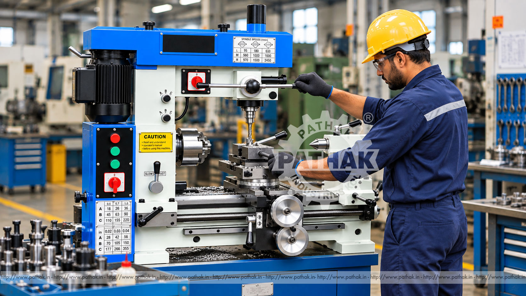
Workshops that produce prototypes, repair components, training pieces, and small production batches often need turning, milling, and drilling without dedicating floor space to three separate machines. A 3 in 1 Lathe Cum Milling and Drilling Machine brings these core metalworking operations together in one compact platform.
The combination format can reduce repeated handling and make a broad range of everyday jobs practical in tool rooms, maintenance departments, technical institutes, fabrication shops, and small engineering units. This guide explains how the machine works, which operations it can perform, how to plan a setup, and what buyers should evaluate before choosing a model.
A 3 in 1 machine combines a conventional centre-lathe arrangement with a vertical milling and drilling head. The lathe spindle rotates the workpiece for turning operations, while the vertical spindle rotates a drill or milling cutter over work secured to the machine table or carriage assembly.
The shared structure makes the machine compact and versatile. It is intended for suitable light and medium workshop tasks rather than replacing every capability of three large, dedicated production machines. Its best use is determined by the work envelope, spindle arrangements, motor power, available feeds, tooling, rigidity, and required accuracy of the selected model.
For turning, the work is secured in a chuck, on a faceplate, or between centres. The headstock spindle rotates the component while a single-point tool moves longitudinally or across its face. This arrangement can produce external diameters, faces, shoulders, tapers, grooves, bores, and compatible threads.
For milling, the cutter rotates in the vertical spindle while the work is held securely below it. Controlled table movement feeds the component past the cutter to produce flats, steps, slots, keyways, pockets, and other suitable features. Cutter selection, workholding, spindle speed, feed, and depth of cut must suit both the material and machine capacity.
For drilling, a drill chuck, collet, or compatible taper tool holds the rotating drill in the vertical head. The quill or head feeds the tool into a securely clamped component. Centre drilling, drilling, countersinking, counterboring, and reaming may be possible when the required tooling and machine specification permit.
A typical combination machine includes the following functional groups:
The exact arrangement varies by model. Buyers should confirm spindle tapers, travels, speed ranges, chuck capacity, motor ratings, feed options, and supplied accessories from the current technical offer.
The turning section can be used for suitable operations such as:
Actual capability depends on component size, chuck and tailstock clearance, work support, material, tooling, and the available spindle and feed settings.
With suitable fixtures and cutters, the vertical head may support face milling, end milling, slotting, keyway cutting, drilling bolt patterns, countersinking, counterboring, and reaming. Small brackets, blocks, plates, machine repair parts, and prototype components are common candidates.
Every milling job requires positive workholding. A machine vice, clamp set, angle plate, rotary fixture, or purpose-built fixture may be needed. The chuck used for turning is not automatically an appropriate fixture for every milling operation.
The principal advantage is process flexibility within a compact footprint. One machine can support several stages of a component, reducing the need to move work between separate areas. This can be valuable where floor space, budget, electrical infrastructure, or production volume does not justify three independent machines.
A shared platform also gives trainees exposure to the principles of rotating work and rotating tools. Maintenance teams can respond to varied repair requirements, while prototype shops can make one-off components without reserving several machines.
The trade-off is that a combination machine must be set up carefully when changing processes. Dedicated machines may offer greater work envelopes, rigidity, power, speed, automation, or production convenience for demanding repetitive work.
A correctly selected 3 in 1 machine can be considered for:
Nominal swing, centre distance, table size, or drilling capacity does not by itself confirm that a job will fit. Review the complete setup, including the chuck or fixture, tool holder, cutter length, tailstock position, jaw projection, clamping access, spindle-to-work clearance, and all required travel.
Start with a component drawing and a written operation sequence. Identify which surfaces establish the datum, how the part will be held for each operation, and how concentricity or feature location will be preserved after repositioning.
Turning work may use a self-centring chuck, independent-jaw chuck, collet, faceplate, or centres. Select the method according to geometry, accuracy, balance, cutting force, and available grip. Long or slender components may require a tailstock centre or steady support.
Milling and drilling work should be clamped against clean, stable reference surfaces. Keep fixtures as low and rigid as practical. Confirm that clamps cannot enter the cutter path and that the table or carriage locks specified for the operation are engaged.
After setup, rotate the spindle by hand with power isolated where appropriate to verify clearance. For milling, trace the intended cutter path and check the full movement envelope before starting.
Turning tools may use high-speed steel or replaceable carbide inserts. The cutting edge should be sharp, securely held, and set to the correct centre height. Excessive tool overhang reduces rigidity and encourages chatter.
Milling cutters include end mills, slot drills, face mills, and speciality cutters compatible with the spindle and collet or arbor system. Drilling tools must be straight, sharp, correctly held, and suitable for the work material. Never exceed the rating of the chuck, collet, arbor, cutter, or spindle.
Speed selection depends on tool material, work material, operation, and effective cutting diameter. A large turning diameter normally requires lower rpm than a small one. Similarly, a large milling cutter runs more slowly than a small drill at the same target cutting speed.
Begin a new setup conservatively. Use a feed and depth of cut the machine can sustain without chatter, spindle overload, work movement, or poor finish. Combination machines generally reward sharp tooling, modest cuts, short overhang, and rigid clamping.
Before changing from turning to milling or drilling, stop and isolate the machine as required. Remove tools that could create a collision, clean chips from reference surfaces, install the correct fixture, and confirm the control and transmission settings for the selected spindle.
Do not assume that the previous operation's locks, guards, speeds, or tool positions are suitable for the next process. Use a repeatable changeover checklist, especially in training or multi-operator workshops.
Install the machine on a rigid, level foundation or stand rated for the total machine, tooling, workpiece, and cutting loads. An unstable support can introduce vibration and alignment errors. Use the manufacturer's mounting points and levelling procedure.
Provide sufficient clearance for carriage movement, tailstock use, access to the vertical head, loading, maintenance, chip collection, and electrical isolation. Lighting should cover both the turning and vertical-spindle work zones without glare.
Electrical supply, earthing, overload protection, phase arrangement, and isolation must match the supplied machine and local regulations. Commissioning should verify spindle rotation, controls, emergency stops, guards, lubrication, and alignment.
Inspect features with instruments appropriate to the tolerance: callipers for general dimensions, micrometers for controlled diameters, dial indicators for runout and alignment, bore gauges for internal dimensions, and gauges for threads or holes.
When a part is transferred from turning to milling, indicate the datum before cutting. Chips or burrs trapped under a vice, fixture, or component can create substantial angular or dimensional error. Take a light trial cut and measure before committing to the final pass.
A combination machine contains rotating chucks, cutters, drills, leadscrews, feed mechanisms, and sharp swarf. Operators must be trained for each process and understand that hazards change when the machine function changes.
Never reach across a rotating chuck or cutter. Do not use compressed air in a way that drives chips into people, bearings, slides, or electrical equipment.
Daily care should include cleaning chips, checking lubrication, inspecting chucks and tool holders, checking guards and controls, and protecting exposed precision surfaces. Keep spindle tapers, ways, and fixture faces clean and free from burrs.
Periodically inspect drive belts or gears, feed screws, gibs, locks, electrical equipment, coolant arrangements, spindle runout, and head alignment. Backlash and looseness should be assessed and adjusted according to the machine documentation.
Maintain a service record covering lubrication, adjustments, tool incidents, electrical work, alignment checks, and replacement parts. Preventive maintenance helps preserve accuracy across all three operating modes.
Prepare a list of representative jobs and compare their maximum diameter, length, width, height, hole size, material, tolerance, surface finish, and batch quantity. Then evaluate:
Share drawings of the largest and most accuracy-sensitive components with Pathak Industries. Final suitability should be confirmed against the current technical specification and the complete proposed setup.
Yes. It combines a lathe spindle and tool slides with a vertical milling and drilling spindle. Each operation still requires the correct tooling, workholding, settings, and setup procedure.
It can support suitable low-volume and varied production work. High-output repetitive jobs may be better served by dedicated or automated machines after cycle time, rigidity, and changeover requirements are evaluated.
Compatible threads may be cut when the machine includes the required leadscrew, gearing, tool, and pitch range. Confirm the specific metric and imperial pitches before purchase.
Suitable slots and keyways can be produced with the correct end mill or slot drill, rigid workholding, sufficient travel, and appropriate speed and feed.
Capacity depends on spindle power and taper, tool type, work material, available feed, rigidity, and spindle-to-work clearance. A listed maximum should always be checked against the actual job.
Use clean datum surfaces, reliable fixtures, dial indicators, table and slide locks, and trial cuts. Recheck alignment whenever the head, vice, fixture, or workpiece is repositioned.
Depending on the machine, useful accessories may include turning chucks, centres, drill chucks, collets, a machine vice, clamp set, milling cutters, boring tools, indicators, and suitable measuring instruments.
Provide component drawings, materials, stock and finished dimensions, required operations, holes and threads, tolerances, finishes, batch quantities, electrical supply, space limits, and preferred accessories.
A 3 in 1 Lathe Cum Milling and Drilling Machine gives compact workshops a flexible platform for rotational and prismatic components. It can support turning, facing, boring, threading, milling, slotting, and drilling when the job remains within the selected machine's work envelope and duty.
Good results depend on more than combining three functions. Rigid installation, careful changeovers, secure workholding, suitable tooling, correct speeds and feeds, disciplined measurement, safe operation, and planned maintenance are essential. Evaluate the full component setup and current technical specification before selecting a model.