Head Office
117, Grand Trunk Road, Salkia Howrah-700013, Kolkata, India
 Hitesh PathakTue, Oct 22, 2024
A valve seat forms the sealing surface between a valve and a cylinder head. Its angle, position, width, surface condition, and relationship with the valve guide all influence whether the valve can close consistently. When a seat is worn, damaged, replaced, or no longer concentric with its guide, it requires controlled machining rather than an approximate hand correction. A vertical seat cutting machine creates a dedicated setup for this work.
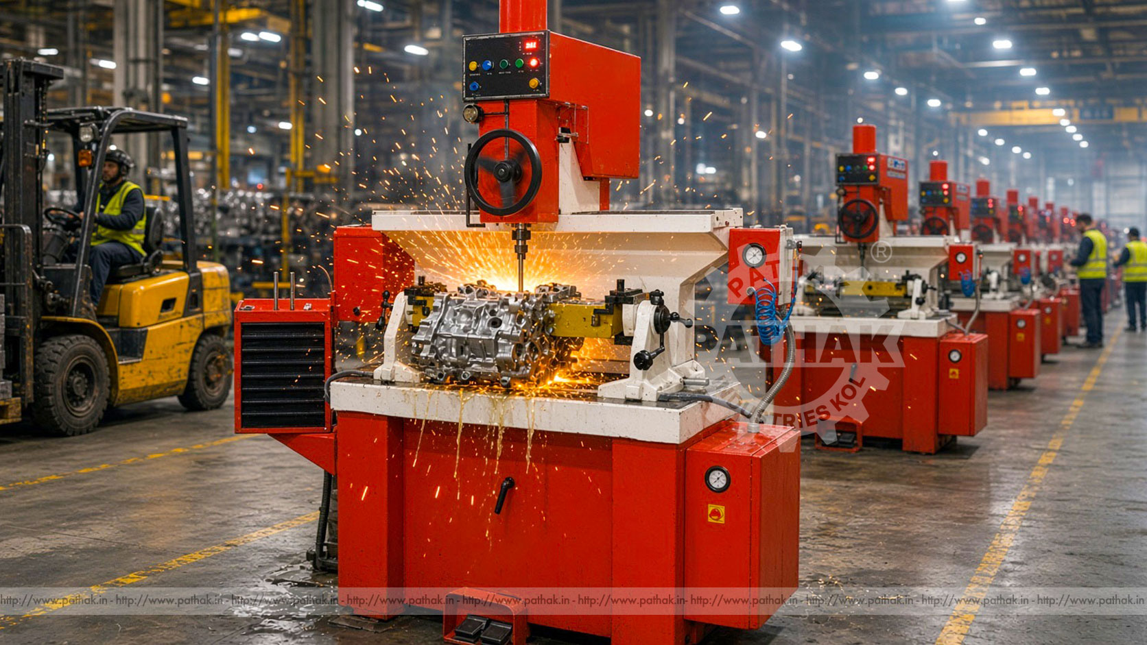
The Vertical Seat Cutting Machine from Pathak Industries is represented by model PVSCM-1000. Its published specification combines a movable spindle head, variable speed, a large clamping table, pneumatic requirements, and seat-diameter coverage intended for different cylinder-head jobs. This guide explains the machining principle, setup sequence, documented capacity, common applications, selection considerations, and maintenance practices relevant to valve-seat work.
A vertical seat cutting machine is specialized equipment used to machine valve seats in cylinder heads and comparable components. The cutting spindle approaches the seat from above while the cylinder head is positioned and clamped on the table below. A pilot associated with the valve guide establishes the working axis, allowing the cutting tool to follow the intended centerline of the valve and guide assembly.
This relationship is central to the process. A seat can appear smooth yet fail to seal correctly if it is not concentric with the valve guide. The machine therefore does more than remove material: it provides controlled spindle positioning, work support, tool movement, and alignment for generating the required seat geometry.
The vertical layout also affects handling and visibility. The component rests on the clamping system while the spindle head is positioned over the selected seat. This arrangement supports access to multiple valve-seat locations across a cylinder head without treating each position as an unrelated setup.
The process begins with inspection and cleaning. Carbon, residue, burrs, and loose contamination can interfere with clamping, pilot seating, or measurement. The valve guide and seat area are examined to determine whether the component is suitable for machining and whether other repair work is required first.
The cylinder head is then supported and clamped on the machine table. A suitable pilot is selected for the valve guide, and the spindle is aligned with that pilot. Correct alignment establishes the reference axis for the cutting tool. The operator selects a cutter suited to the intended seat angle and diameter, sets the spindle condition, and advances the tool in a controlled manner.
Only the material needed to restore the seat should be removed. After cutting, the seat is cleaned and inspected for geometry, surface condition, position, width, and concentricity according to the repair procedure. The matching valve and guide condition must also be considered; machining one element cannot compensate for an unsuitable part elsewhere in the assembly.
The valve stem travels through the guide, so the guide defines the valve’s operating axis. The seat must share that axis closely enough for the valve face to contact it consistently around the circumference. If the seat is offset or angled incorrectly, contact may be uneven even when the surface looks freshly machined.
A properly selected pilot helps the spindle and cutter follow the guide axis. Pilot condition is therefore important: wear, incorrect size, dirt, or damage can introduce error before cutting begins. The guide itself must also be evaluated. Excessive guide wear can prevent a stable reference and may need attention before the seat is machined.
This is why a valve-seat job should be treated as a complete alignment and inspection process rather than simply a cutting operation. Setup accuracy has a direct effect on the usefulness of the finished seat.
The PVSCM-1000 has a published spindle dimension of 90 mm and a 0.75 kW / 1 HP spindle motor. Maximum spindle travel is listed at 150 mm, and spindle-head travel is 40 mm front-to-back and 1200 mm left-to-right. These movements allow the head to be positioned across different working locations on the clamped component.
Spindle speed is variable from 40 to 300 RPM. This range gives the operator documented adjustment for matching an approved cutter and seat operation. The product table lists a maximum spindle tilt of 20 degrees to either side of zero and identifies 45-degree and 30-degree seat-angle work. Exact tooling and procedure must be selected for the cylinder-head specification being repaired.
The clamping table measures 1300 × 550 mm. Standard seat-diameter capacity is published from 28 to 45, with an optional range from 18 to 60. Distance from table to spindle is listed at 400 mm, while clamping-block travel is 130 mm front-to-back.
Electrical requirements are published as three-phase, 15 amp, 1 HP, and the pneumatic requirement is 100 PSI / 8 bar. Listed floor-space dimensions are 1600 × 900 × 2200 mm. Approximate machine weight is 950 kg, and gross weight is 1200 kg. Installation planning should confirm current utility and foundation requirements before delivery.
The primary seat angle creates the sealing contact with the valve face. Additional angles may be used as part of an approved seat profile to position or control the contact area. The product specification identifies 45-degree and 30-degree seat-angle capability, but the required geometry must come from the engine or component repair data—not from a general assumption.
Seat width and position are as important as the nominal angle. A contact band that is too wide, too narrow, too high, or too low can affect sealing and heat transfer. Material should be removed in deliberate increments, with inspection between cuts. Overcutting can recess the valve or change geometry beyond the acceptable repair limit.
The cutter must remain sharp and appropriate for the seat material. A worn or unsuitable cutting edge can produce chatter, tearing, or an inconsistent finish. Cutter storage and handling should protect the edge and preserve the geometry established during tool preparation.
A Vertical Seat Cutting Machine is relevant to automobile engine rebuilding, cylinder-head reconditioning, commercial-vehicle maintenance, engine remanufacturing, tractor and agricultural-engine repair, generator-engine service, and other workshops responsible for suitable valve-seat work.
The machine can support individual repair jobs as well as recurring cylinder-head batches. In a specialized reconditioning shop, it may form one station in a broader process that includes disassembly, cleaning, crack inspection, guide inspection or replacement, surface work, valve servicing, seat machining, final cleaning, and assembly inspection.
Different cylinder heads present different materials, dimensions, valve arrangements, and handling needs. The published table and travel provide the starting point for assessing fit, but the actual head, supports, tooling, and spindle access must be evaluated together.
Good seat cutting begins with good preparation. The cylinder head should be cleaned sufficiently for reliable support and inspection. Gasket remnants, loose deposits, and debris should not remain beneath clamping or locating surfaces. The head is inspected for damage that may make machining inappropriate or require another repair stage first.
Valve guides should be checked before the seats. Because the pilot uses the guide as its reference, an unsuitable guide can undermine the alignment of the entire operation. The operator should also confirm the intended seat angles, permissible material removal, finished contact position, and inspection method.
Supports and clamps must hold the cylinder head securely without distorting it. The component should remain stable as the spindle is aligned and cutting force is applied. Clamps must not obstruct spindle travel or contact vulnerable surfaces.
Select a clean, undamaged pilot matched to the guide and an approved cutter matched to the required seat. Position the spindle head over the work using the machine’s front-back and left-right travel. The tilt provision allows the head to be aligned with valve guides that are not perpendicular to the table.
Alignment should be established gently; forcing a pilot into position can damage the guide or create a false setup. Check cutter clearance around the chamber, head casting, clamps, and nearby seats. Select spindle speed according to the approved tooling and material requirements within the published 40–300 RPM range.
Use a controlled feed and observe the cut. Excessive material removal in one pass may affect finish or tool behavior. Stop and inspect whenever the surface, sound, resistance, or chip pattern indicates that the setup should be reviewed.
The vertical configuration supports the component on a working table while positioning the spindle above it. For suitable cylinder heads, this can simplify access and allow the spindle head to travel between different valve-seat locations without unloading the component after every operation.
These capabilities support the process but do not replace cylinder-head inspection, correct pilot selection, competent tooling, or verification of the finished seat.
Begin with representative cylinder heads. Record overall size, valve locations, guide angles, seat diameters, seat materials, required angles, and the heaviest component to be handled. Compare these details with the table size, spindle clearance, head travel, tilt, standard or optional diameter range, and clamping movement.
Review the number of jobs, variation between head types, operator experience, available inspection equipment, tooling inventory, air supply, electrical supply, lifting requirements, and service access. If the planned work includes seats outside the standard 28–45 range, confirm the optional 18–60 arrangement and compatible tooling before ordering.
Share actual component information and repair objectives with Pathak Industries. A meaningful machine selection depends on the cylinder head and required process, not the product name alone.
Only trained personnel should operate the machine. Before cutting, inspect clamps, supports, pilot, cutter, spindle, guards, controls, air connections, and the work area. Confirm that the head is stable and that the spindle can move without striking clamps or the casting.
Keep hands clear of the rotating cutter and stop the spindle before measuring, cleaning, adjusting, or moving tooling. Chips and sharp edges should be handled with appropriate tools and protective measures. Isolate electrical and pneumatic energy before maintenance according to the supplied procedure.
Routine care includes cleaning the table and slides, inspecting spindle movement, maintaining lubrication, checking pneumatic condition, examining electrical controls, protecting pilots and cutters, and recording abnormal noise, runout, vibration, or finish changes. Service intervals and adjustment procedures should follow the machine documentation.
It machines valve-seat surfaces in suitable cylinder heads and comparable components. The seat is cut in alignment with the valve-guide axis using an appropriate pilot and cutter.
The published standard range is 28 to 45, with an optional range from 18 to 60. Buyers should confirm the required units, tooling, and complete configuration for their components.
The PVSCM-1000 has a published variable spindle-speed range of 40 to 300 RPM. The operating setting should match the cutter, seat material, diameter, and approved machining procedure.
The pilot references the valve guide so the cutter can be aligned with the valve’s operating axis. Correct pilot fit and guide condition are essential for useful concentricity.
The product table lists spindle tilt to either side of zero, allowing alignment with angled guide positions within the documented range. The cylinder head must still be supported and clamped correctly.
The published data states three-phase, 15 amp, 1 HP electrical requirements and an air requirement of 100 PSI / 8 bar. Current installation requirements should be confirmed before preparing the site.
Provide cylinder-head dimensions and weight, valve arrangement, guide angles, seat diameters and materials, required seat geometry, expected workload, available utilities, tooling needs, and handling requirements.
A Vertical Seat Cutting Machine brings together the key elements of valve-seat work: stable cylinder-head support, guide-based alignment, controlled cutter movement, variable spindle speed, and inspection between machining stages. Its value is realized when each part of that process is treated with equal care.
The PVSCM-1000 offers documented travel, table size, tilt, speed, utility, and seat-diameter information for application planning. By matching those figures to real cylinder heads and by maintaining pilots, cutters, clamping systems, and inspection practices, a reconditioning workshop can build a disciplined process around accurate seat machining.