Head Office
117, Grand Trunk Road, Salkia Howrah-700013, Kolkata, India
 Hitesh PathakWed, Jun 24, 2026
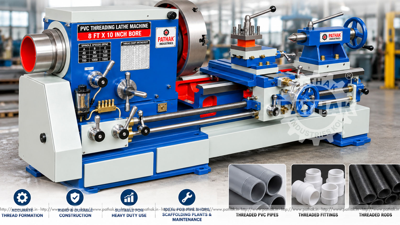
Producing a usable thread on PVC pipe requires control over workholding, alignment, speed, tool geometry, engagement length, and surface condition. If the pipe is clamped unevenly or the cutting tool does not follow the centreline, the result may be tapered, torn, oversized, or difficult to assemble. A PVC Threading 8 ft 10 Inch Bore Lathe Machine provides a lathe-based arrangement for supporting suitable tubular work and guiding the selected threading process.
The Pathak Industries product page provides an HC model table covering maximum collet capacities from 20 to 60 mm, spindle hollows from 25 to 62 mm, model-specific spindle speeds, turret-slide strokes, cross-slide travel, and bed dimensions. Because this published table does not verify a 10-inch through-bore, buyers should treat the product title as configuration terminology and obtain written confirmation of the required pipe diameter, bore, length, and workholding arrangement before ordering.
A PVC threading lathe rotates or supports a pipe while guided tooling produces an external thread. Depending on the confirmed setup, the working tool may be a cutter, die arrangement, or another suitable thread-forming system. The purpose is to hold the pipe concentrically and maintain a controlled relationship between work rotation, tool position, and feed.
PVC behaves differently from metal. It can deflect under excessive clamping, soften with heat, chip at an unsuitable cutting condition, and develop poor thread form if the tool is blunt. Machine rigidity remains important, but successful production also depends on a process developed specifically for the pipe material and joint requirement.
The operator prepares the pipe end, cleans the holding area, and secures the work in the appropriate collet or chuck arrangement. Long pipe must be supported so its axis agrees with the spindle and so unsupported material cannot whip. The threading tool is set to the required centre and approach position.
During the cycle, the work and tool move relative to one another to generate the specified pitch and thread profile. The tool is withdrawn without damaging the newly produced thread, and the pipe is deburred and inspected. Exact speed, feed, depth, and number of passes must come from the approved process for the material and tooling.
The product table includes HC-60GN, HC-50GN, HC-40GN variants, HC-32G, HC-25G, HC-25S, and HC-20S. Listed maximum collet capacities are 60, 50, 40, 32, 25, and 20 mm according to model. Spindle hollow figures range from 62 mm on HC-60GN down to 25 mm on HC-20S.
These values show that capacity varies substantially across the range. The actual pipe outside diameter, wall thickness, coupling form, and required pass-through clearance must be checked against the selected model. A nominal machine or marketing name should never replace a dimensioned application review.
Published spindle-speed ranges vary by model. HC-60GN lists 90–1000 rpm; HC-50GN and one HC-40GN column list 100–1050 rpm; another HC-40GN entry and HC-32G list 165–1500 rpm; HC-25G lists 275–900 rpm; and HC-25S and HC-20S list 650–1660 rpm.
The correct operating speed is not automatically the highest available value. Pipe diameter, material grade, wall section, tool type, cut depth, support, and heat generation all matter. Initial trials should use conservative parameters and observe chip form, surface condition, vibration, and dimensional results.
The effective turret-slide stroke is listed from 100 to 180 mm depending on model. The maximum distance from spindle nose to turret face ranges from 300 to 430 mm. Transverse cross-slide travel is 95 or 150 mm, while longitudinal cross-slide travel is listed as 300 mm throughout the table.
Travel values define available movement, not guaranteed clearance for every holder and pipe. Selection should include a setup drawing with the collet or chuck, pipe projection, toolholder, threading tool, approach, and withdrawal position. This prevents discovering an interference after tooling is purchased.
PVC pipe can deform when clamping pressure is concentrated over a small area. The holding method should distribute force sufficiently to transmit torque without crushing or marking the pipe. Clean, size-matched collets or suitable jaws help preserve concentricity.
The operator should check pipe roundness and straightness before loading. Dirt or chips between the work and holding surface can shift the centre. For thin-wall sections, internal support or a specially developed gripping arrangement may be required; this must be confirmed for the application rather than improvised.
The “8 ft” wording indicates that long work handling is central to the requested application, but the published model table lists bed lengths from 960 to 1375 mm rather than confirming an eight-foot working span. Long pipe therefore requires a verified support arrangement outside the immediate machine envelope.
Roller supports or another suitable system should maintain the spindle centreline and allow controlled movement without binding. The projecting end must be guarded so nobody can enter its sweep. Bent pipe, misaligned supports, or excessive speed can create dangerous whipping and poor threads.
Tool geometry must match the required thread profile and PVC material. A sharp edge helps cut cleanly with less heat and force. Toolholders need adequate rigidity and minimum practical overhang. Any insert, cutter, or die should be inspected for wear and material build-up before a batch begins.
A controlled process specifies pitch, major and minor diameter, engagement length, chamfer, speed, feed, and inspection method. Where a mating fitting is available, functional checking may complement dimensional measurement, but it should not replace required gauges or documented acceptance criteria.
Excess heat can soften PVC and smear the thread surface. A blunt tool, excessive speed, heavy cut, or poor chip evacuation can increase temperature. Operators should use validated parameters and allow chips to clear without wrapping around the pipe or tool.
Thread finish should be continuous, with no tearing, melted areas, large burrs, or incomplete crests where the specification requires otherwise. The pipe end may need a controlled chamfer to help assembly and protect the first thread.
A properly configured PVC threading lathe may support pipe fabrication shops, water-management component production, construction-material suppliers, maintenance workshops, and manufacturers of compatible threaded fittings or assemblies. It may also be useful where repeated pipe lengths need a consistent threaded end.
Suitability depends on the exact material and joint design. Pressure service, chemical exposure, temperature, sealing method, and installation rules can impose additional requirements beyond machine capability. The finished component must be assessed for its actual service.
Guided slides and defined workholding help maintain the tool-to-pipe relationship throughout the cut.
Documented settings and stops can reduce variation between similar parts after the first-piece process has been approved.
The turret arrangement supports planned positioning of suitable tools, subject to the bore and stroke listed for the selected model.
The HC range provides several collet capacities and speed ranges so the machine can be matched more closely to actual work.
The HC table lists a floor-space requirement of 3 × 1 m across the model range. This does not include the extra area needed for long pipe, loading, supports, operator movement, guarding, chip collection, electrical access, and maintenance.
The floor should be stable and the machine levelled according to its instructions. Lighting should make the tool and pipe end clearly visible. Long material routes should be separated from pedestrian traffic, and racks should prevent pipe from rolling unexpectedly.
Rotating pipe, chucks, collets, lead screws, and tools present entanglement and pinch risks. Guards must remain installed, chuck keys and setup tools must be removed, and loose clothing, gloves near rotation, jewellery, and unsecured hair must be controlled according to site procedure.
The machine must stop and be isolated before clearing wrapped chips, measuring near moving parts, changing tools, or adjusting supports. Operators should never steady rotating pipe by hand. Emergency stops and braking behaviour should be checked before production.
First-piece and periodic inspection can include thread pitch, major diameter, minor diameter where applicable, effective length, end squareness, chamfer, surface condition, and fit with the specified counterpart. The method and frequency should reflect the component requirement.
Records should link results to the machine, tool, material batch, operator, settings, and date. A trend toward oversize, taper, roughness, or poor fit can reveal tool wear, workholding movement, pipe variation, or slide adjustment needs.
Keep slides, screws, racks, and workholding clean of PVC chips. Inspect lubrication points, belts or gears, fasteners, guards, collets, chuck jaws, toolholders, electrical controls, and long-work supports. Worn or damaged holding surfaces should not be used.
Periodic checks should cover spindle condition, slide backlash, turret indexing, alignment, drive tension, motor ventilation, and electrical connections. Maintenance must follow the machine schedule with energy isolated and guards restored before testing.
Provide the actual pipe sample or drawing, outside and inside diameters, wall thickness, length, material grade, thread form, pitch, engagement length, tolerance, batch size, and required output. Confirm collet capacity, spindle hollow, speed range, tool travel, support arrangement, and working clearance in writing.
The title “10 Inch Bore” should not be assumed to describe the published HC table, whose largest listed spindle hollow is 62 mm. If a 10-inch through capacity is essential, Pathak Industries must confirm a separate suitable configuration before quotation and manufacture.
Maximum collet capacities range from 20 to 60 mm, while listed spindle hollows range from 25 to 62 mm depending on model.
No. The published table does not substantiate that dimension. Any required 10-inch through-bore configuration must be confirmed directly in writing.
Long pipe may be processed only with a confirmed machine configuration and properly aligned external support. The listed bed dimensions alone do not establish an eight-foot working capacity.
The table lists model-dependent ranges from 90–1000 rpm up to 650–1660 rpm. The safe operating value depends on pipe, diameter, tooling, and support.
PVC can deform under concentrated clamping. A suitable collet or jaw arrangement distributes force while holding the pipe securely and concentrically.
Use the approved drawing and inspection plan for pitch, diameters, length, profile, finish, chamfer, and functional fit where applicable.
The model table states 3 × 1 m, excluding long-material supports, guarding, loading routes, operator clearance, and maintenance access.
Provide pipe samples or drawings, dimensions, material, thread specification, length, quantity, output target, support needs, utilities, and any essential through-bore requirement.
A PVC threading lathe can provide controlled alignment and repeatable tooling for suitable pipe work, but machine selection must be driven by verified dimensions. The Pathak Industries page offers detailed HC model data for collet capacity, spindle hollow, speeds, travel, and bed size. Matching that data to the real pipe, supporting long stock correctly, controlling heat, and inspecting every approved characteristic are essential for safe and consistent production.