Head Office
117, Grand Trunk Road, Salkia Howrah-700013, Kolkata, India
 Hitesh PathakMon, Mar 31, 2025
Large machine beds, frames, plates, columns, and fabricated structures often need long, straight, flat surfaces that cannot be handled conveniently on a small machine tool. A planing machine addresses this work by carrying the clamped component back and forth beneath one or more cutting tools. Its long table travel and substantial working clearance make it suitable for components whose size and mass are central to the machining problem.
The Planing Machine from Pathak Industries is offered in published table-stroke sizes from 6 feet through 20 feet. The range provides different table travel, cross-rail clearance, planing width, power, tool-post arrangements, and approximate machine weights. This guide explains how planing works, which surfaces it can produce, how to compare the available sizes, and what setup, tooling, inspection, safety, and maintenance factors influence practical results.
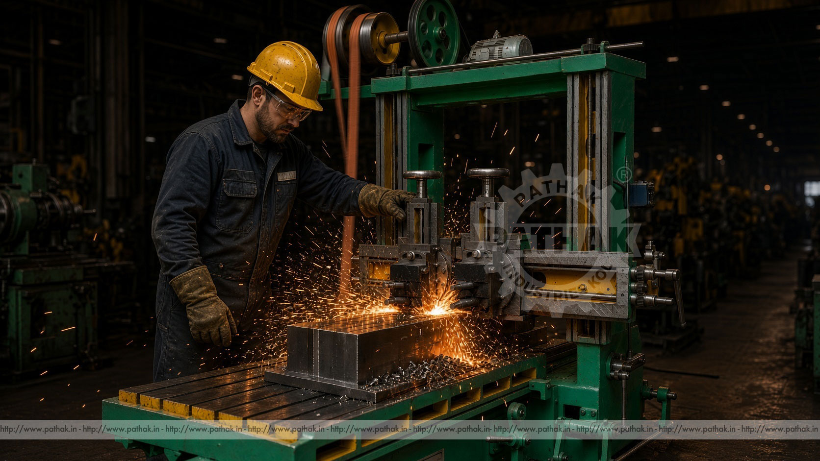
A planing machine is a reciprocating machine tool in which the workpiece is secured to a moving table. The table carries the job past stationary or incrementally fed cutting tools mounted on a cross rail. Material is removed during the cutting stroke, and the table then returns so the next stroke can begin.
This arrangement differs from a shaper, where the cutting tool typically reciprocates over a stationary job. By moving the table and workpiece, a planer can accommodate long, heavy components and machine broad surfaces over a substantial distance.
Planing is used primarily for flat, stepped, parallel, vertical, or angular surfaces, depending on the tool position and machine arrangement. Suitable tooling and setup can also support grooves, slots, guideways, and related linear features. The actual operation must remain within the selected model’s work envelope and tool capability.
The component is located and clamped to the table using approved fixtures, clamps, stops, and supports. The cross rail and tool posts are positioned so the cutting edge approaches the required surface with adequate clearance. Cutting depth, feed, table stroke, and operating speed are then established for the material and tool.
During the forward cutting stroke, relative motion between the workpiece and tool removes a chip along the component. At the end of travel, the machine reverses. The return stroke does not normally perform the same cutting work and is therefore set to bring the table back efficiently before the tool receives its next feed increment.
The published range reflects this difference: the 6-foot through 14-foot machines list cutting speed at 480 per minute and return speed at 640, while the 16-foot and 20-foot versions list 384 cutting and 412 return. These source values should be confirmed with their current units and model documentation during selection.
A long component creates several challenges. Its weight must be supported without introducing distortion, the full surface must fit within travel, cutting force must pass through a stable load path, and the tool must remain aligned over the entire stroke. A planer addresses these needs with a long bed, reciprocating table, rigid columns, cross rail, and guided tool posts.
The table provides multiple locations for clamping and support. The cross rail spans the work area and positions tools above the component. Larger published sizes use two cross-rail tool posts, allowing the setup to be arranged for suitable parallel or staged work. The 6-foot and 8-foot versions list one cross-rail tool post, while the 10-foot through 20-foot versions list two.
Machine capacity does not remove the need to evaluate workpiece deflection. Long, thin, or irregular parts may require distributed support and a balanced clamping plan so the machined surface remains correct after the clamps are released.
The Pathak range lists 6-foot, 8-foot, 10-foot, 12-foot, 14-foot, 16-foot, and 20-foot table-stroke configurations. Their published maximum table travels are 72, 96, 120, 144, 158, 192, and 240 inches respectively. Metric figures are also provided in the source table; where legacy conversions conflict, buyers should use the current approved specification supplied for the selected model.
Maximum planing width progresses from 36 inches on the 6-foot version to 48 inches on the 8-foot model, 54 inches on the 10-foot model, 60 inches on the 12-foot and 14-foot versions, and 72 inches on the 16-foot and 20-foot machines.
Maximum height under the cross rail is published as 36 inches for the 6-foot machine, 48 inches for the 8-foot, 54 inches for the 10-foot, 60 inches for the 12-foot, 14-foot, and 16-foot configurations, and 72 inches for the 20-foot model.
These three values—travel, width, and height—form the initial working envelope. Tooling, clamps, supports, approach, overtravel, and handling clearance also occupy space, so a workpiece that merely matches the headline dimensions may not represent a practical setup.
The published drive method is individual electrical drive across the range. Required power rises with machine size: 3 HP for 6 feet, 5 HP for 8 feet, 7.5 HP for 10 feet, 10 HP for 12 and 14 feet, 15 HP for 16 feet, and 20 HP for 20 feet.
Approximate machine weights are listed as 3500, 6000, 9000, 11000, 13000, 18000, and 20000 kg in ascending size order. These values affect foundation design, lifting, transport, installation, and floor planning. The selected machine should be reviewed by the responsible site team before delivery.
Tool-post down feed is listed at 8 inches on the 6-foot through 14-foot versions and 10 inches on the larger models. The source table associates metric entries with these figures, but current documentation should be used where a conversion appears inconsistent.
The primary application is producing a long flat plane on a large component. Roughing passes remove scale or excess material, while later passes approach the required size and finish. Inspection across the surface confirms whether straightness, flatness, and parallelism meet the drawing.
Tool positions and feeds can be arranged to machine related surfaces or steps. The setup must preserve the dimensional relationship between those features, especially when the workpiece is repositioned or several tools are used.
Appropriate tool-head positioning can support vertical or angular faces within machine and tooling capability. Cutting force, tool clearance, chip flow, and clamping should be reviewed for the direction of each operation.
Planing may be used to generate straight slots, guideways, or other long linear features. The cutting sequence and tool geometry should prevent excessive side loading and maintain the intended relationship to reference surfaces.
The product is associated with automotive, die and mould, aerospace, textile machinery, medical equipment, plastic-processing machinery, defence, and allied engineering applications. A planer can also be relevant to general machine-building, repair, fabrication, and heavy equipment facilities.
Example work may include machine beds, base plates, frames, slides, tables, columns, bolsters, structural blocks, die plates, and large repaired components. These examples do not guarantee suitability; each material, dimension, feature, tolerance, and finish requirement must be checked against the selected model.
A planer is particularly useful when the component’s length, mass, or geometry makes another machining arrangement less practical. Production quantity also matters because long setup and stroke times may be justified differently for one repair component than for a recurring product.
Clamping must stop the workpiece from shifting under cutting force while avoiding unnecessary distortion. Begin with clean table and locating surfaces. Use supports beneath structurally appropriate areas and verify that clamps transfer force through stable sections of the job.
The setup should allow the cutting tool to complete its stroke without striking clamps, stops, supports, or unmachined projections. Table reversal and overtravel also need clearance. Before powered cutting, the complete path should be checked according to the approved procedure.
Long fabricated components may contain residual stress. Removing material from one surface can release that stress and change shape. The process plan may require balanced cuts, intermediate unclamping or inspection, or a defined machining sequence based on the component requirements.
Planer tools are selected according to material, operation, depth of cut, feed, rigidity, and finish requirement. The toolholder should minimize unnecessary overhang, and the cutting edge must have sufficient clearance throughout the stroke.
Roughing tools prioritize stable material removal, while finishing tools are prepared for lighter cuts and surface requirements. If several tool posts operate, their positions and loads should be planned so the machine and workpiece remain stable.
Cutting speed and feed should follow the tool, material, and machine documentation. Sparks or glowing chips are not a target condition and should not be inferred from an illustrative image. Abnormal heat, noise, vibration, or chip behavior calls for stopping and reviewing the process.
Large surfaces require an inspection plan suited to their dimensions. Measurements may include thickness, step height, straightness, flatness, parallelism, angle, slot position, and finish. Suitable straightedges, levels, indicators, measuring instruments, or other verified equipment are chosen according to the drawing.
Take measurements at planned locations rather than only at one end. Thermal condition can affect large components and machines, so inspection practice should account for the process and required accuracy. Chips, burrs, and dirt must not remain between the measuring tool and surface.
Intermediate checks help prevent excessive material removal. Once a large surface is cut below its allowable size, correction may be difficult or impossible.
The product record lists an instruction manual and tool kit as standard accessories. Optional items include a digital readout, drilling head, milling head, motor, panel board, and reduction gearbox. The purpose and compatibility of each option should be confirmed for the selected planer size.
A digital readout may assist position monitoring when integrated with the appropriate axes. Drilling or milling heads can broaden the planned workflow for suitable features, but they do not automatically convert every planer setup into a complete machining center. Work access, power, tool interface, and process requirements still need review.
Begin with the largest and smallest representative components. Record overall length, width, height, weight, material, surfaces to be machined, stock allowance, tolerance, finish, handling method, and required output. Compare these needs with table travel, planing width, cross-rail clearance, table dimensions, tool-post travel, and machine power.
Allow additional capacity for fixtures, supports, tool approach, table reversal, and future work. Also consider foundation, lifting, transport access, electrical supply, chip management, operator space, and maintenance clearance. Approximate machine weight increases substantially across the range and must be part of site planning.
Share component drawings and process details with Pathak Industries. Where legacy table conversions conflict, request the current approved dimensional sheet before foundation or fixture work begins.
A reciprocating table creates a large moving zone and possible crushing or impact hazards. The travel area must remain guarded or controlled, and no person should stand where the table or workpiece can reach. Long components, clamps, and projections can extend beyond the apparent table outline.
Only trained operators should run the machine. Verify workholding, tooling, guards, stops, and clearances before starting. Stop and isolate the machine before measuring, adjusting, removing chips, changing a tool, or entering the travel zone.
Heavy workpieces require approved lifting and rigging. Chips can be sharp and hot, so they should be handled with suitable tools and protective measures. Unexpected noise, vibration, movement, or tool behavior requires immediate investigation.
A planer depends on clean, lubricated guideways and stable alignment over a long stroke. Maintain lubrication, remove chips, protect sliding surfaces, and inspect table motion, drive components, cross-rail movement, tool posts, fasteners, controls, guards, and electrical systems according to the supplied schedule.
Wear or contamination on guideways can influence movement and surface results. Tool posts and feed mechanisms should remain free of excessive play. Foundation condition and leveling also deserve periodic attention on a large reciprocating machine.
Record maintenance, abnormal observations, and dimensional trends. A gradual change in flatness or finish may reveal a developing mechanical, tooling, setup, or lubrication issue before a major failure occurs.
It machines long flat, parallel, stepped, vertical, angular, or slotted surfaces on suitable large components by reciprocating the clamped workpiece beneath one or more cutting tools.
On a planer, the workpiece and table reciprocate while the cutting tools are mounted on the machine structure. On a typical shaper, the tool reciprocates over a stationary workpiece.
The product range lists 6-foot, 8-foot, 10-foot, 12-foot, 14-foot, 16-foot, and 20-foot configurations.
The largest models list a maximum planing width of 72 inches. Smaller configurations provide published widths from 36 to 60 inches.
Suitable tool-post arrangements may support related surfaces or staged operations, provided tooling, load, clearance, feed, and the component setup are planned correctly.
Large components can deflect or distort under their own weight, clamping force, residual stress, or cutting load. Distributed, stable support helps preserve the intended geometry.
Provide component drawings, dimensions, weight, material, machining surfaces, stock allowance, tolerance, finish, production quantity, lifting plan, available power, and installation space.
A Planing Machine offers a direct method for machining long, heavy workpieces through a controlled reciprocating-table cycle. The Pathak range spans several travel and clearance classes, allowing workshops to compare machine size with component geometry rather than forcing large work onto an unsuitable platform.
The best results come from treating table travel, support, clamping, tool position, cutting conditions, inspection, foundation, and maintenance as one process. A carefully selected and correctly installed planer can then provide a stable production or repair platform for large flat and linear surfaces.