Head Office
117, Grand Trunk Road, Salkia Howrah-700013, Kolkata, India
 Hitesh PathakTue, Oct 7, 2025
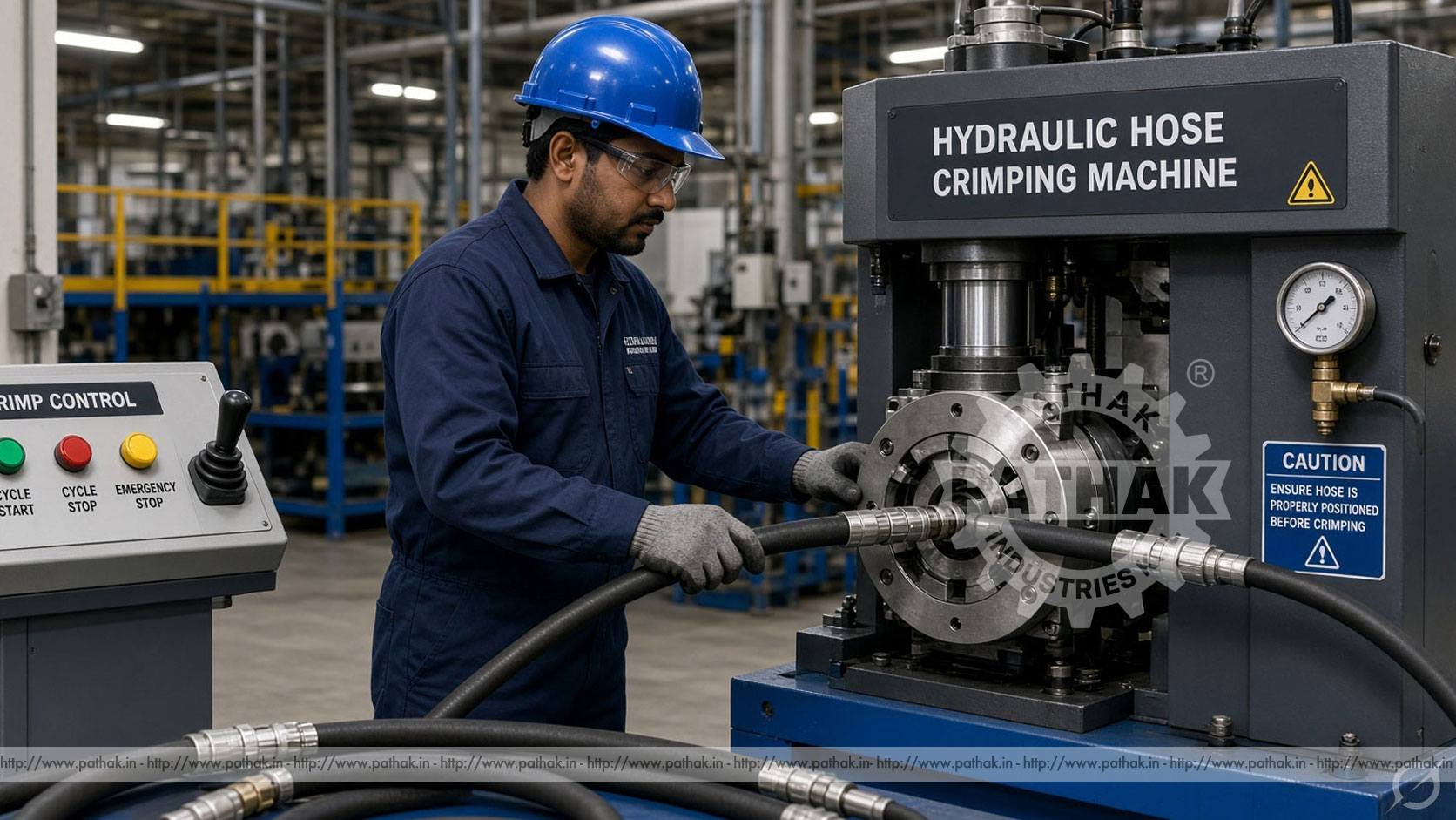
A hose assembly depends on the connection between its flexible body and end fitting. That connection must be formed evenly, to a verified finished diameter, without damaging the hose, ferrule, nut, or fitting. The Nut Crimping Machine provides a controlled method for this operation by closing segmented dies concentrically around a prepared assembly. It is relevant to hose service, equipment repair, plumbing-product preparation, and production facilities that need repeatable fitting retention.
The machine’s published crimping range is 6–51 mm, expressed on the product page as 1/4–2 inches, and ten moulds are listed. The record also gives a maximum open diameter of 114 mm. These dimensions help describe the machine’s working envelope, but they do not make every hose and fitting combination automatically compatible. The correct die, target crimp diameter, component preparation, and validation method must come from the hose-and-fitting system being assembled.
A nut crimping machine is a specialised press that reduces a ferrule or fitting section around a hose or related cylindrical assembly. Multiple die segments move inward together, applying force around the circumference rather than pressing from only one direction. This concentric closure helps maintain the round form of the assembly while producing mechanical retention between compatible components.
In this product context, “nut” refers to the fitting or end-connection assembly being secured. The machine is not intended to manufacture ordinary threaded nuts from raw material. It works with prepared hoses, ferrules, fittings, couplers, or title-specific parts that have already been selected as a compatible assembly.
The crimping head contains matched die segments arranged around a central opening. When the cycle begins, the machine drives those segments inward. Each segment supports part of the circumference, so their coordinated movement reduces the fitting toward the established crimp diameter. At the end of the cycle, the dies reopen and the assembly can be removed for measurement and inspection.
Uniform movement matters because an off-centre or incorrect setup can produce an oval crimp, uneven retention, damaged reinforcement, or interference with the fitting. Dies must be clean, correctly seated, and intended for the required diameter. The fitting should be inserted to the specified position before closure begins.
The product page lists a crimping range from 6 to 51 mm and a maximum open diameter of 114 mm. Crimping range generally describes the diameters the configured machine and tooling are intended to process, while maximum opening helps indicate the largest assembly that can be introduced into the open head. These figures describe different aspects of access and forming and should not be treated as interchangeable.
The listed range must be compared with the finished crimp diameter specified for the exact hose, ferrule, and fitting combination. Outer diameter alone is not enough to establish compatibility. Construction, reinforcement, wall thickness, ferrule geometry, and fitting design all affect how the assembly responds to compression.
The published product data lists ten moulds. Each die set covers a defined working interval and has its own closed geometry. Selecting the wrong die can prevent the machine from reaching the required diameter, create excessive force, mark the ferrule, or leave the connection under-crimped. Operators should use a controlled chart or job instruction linking each assembly to the correct die and target.
Before loading, inspect every segment for wear, cracks, contamination, and mismatched identification. A single incorrect segment can disturb concentricity. Die seats should be cleaned so the tooling closes without obstruction. When changing a set, all pieces should be replaced together and secured according to the operating instructions.
Crimp quality begins at cutting and preparation. The hose should be cut square using a method suitable for its construction. Loose debris must be removed so it does not enter the assembly or interfere with insertion. Where skiving or another preparation step is specified, it should be completed to the prescribed length without damaging the reinforcement.
The fitting, nut, ferrule, and hose must belong to an approved combination. Components that merely appear to fit together are not necessarily engineered to work as a system. Insert the fitting to the required depth and use an assembly mark where appropriate; that mark can reveal movement during crimping. Lubricants should be used only when permitted by the component procedure.
First identify the job and confirm the component part numbers. Select the specified die set, install it correctly, and establish the target crimp setting. Prepare and assemble the hose and fitting, then position the crimp zone centrally within the dies. Keep hands and loose items away from the closing head before starting the cycle.
After the dies reach the established position, allow the head to reopen fully before removing the assembly. Measure the crimp at the specified locations with suitable calibrated equipment. Record the result when traceability is required. A first-off inspection should be completed whenever tooling, components, settings, or product batches change.
The product record lists optional swept-volume configurations of 2.5, 5, or 10 litres and an optional system pressure of 31.5 MPa. Power options are stated as 3 or 4 kW, while the listed voltage choices are 220, 240, 380, and 415 V. The exact motor and electrical arrangement must be selected to suit the installation and confirmed in the final offer.
Published machine dimensions are 730 × 480 × 740 mm, with a package size of 800 × 530 × 870 mm. Net and gross weights are listed as 245 and 260 kg respectively. These values assist with bench or floor planning, freight, unloading, and access, but the installation drawing should be checked before foundations, lifting arrangements, or service clearances are finalised.
An efficiency figure of 200 pieces per hour appears in the source data. This should be understood as a published machine figure under suitable conditions, not a guaranteed output for every assembly. Real production depends on hose preparation, fitting insertion, die changes, operator handling, inspection, batch size, and workflow around the crimper.
A nut crimping machine can support hydraulic-hose workshops, industrial maintenance departments, equipment-repair facilities, plumbing-product operations, and assembly plants. It may be used for new assemblies or controlled replacement work where compatible fittings must be secured to prepared hose.
In a service shop, flexibility and organised die storage may be important because job types change frequently. In a production plant, repeatable setup, component traceability, inspection records, and efficient material presentation may matter more. The same crimping principle serves both environments, but their handling and quality systems differ.
Finished diameter is a primary check, but it is not the only one. Measure at the locations and orientations defined by the component provider. Inspect the ferrule for cracks, severe marking, uneven closure, or unexpected deformation. Confirm that the fitting has not moved from its insertion position and that the connection remains correctly aligned.
Some applications require additional validation such as proof testing, leakage testing, cleanliness control, or destructive qualification. These requirements come from the hose system and its service conditions, not from the crimping machine alone. A crimp that looks neat may still be incorrect if the wrong components or target diameter were used.
An oversized finished diameter may provide inadequate retention. Check the target, setting, die selection, component identity, and whether the cycle reached its required endpoint.
Excessive reduction can damage the fitting, ferrule, reinforcement, or inner hose. Do not compensate for an incorrect component combination by simply increasing compression.
Inspect for mismatched, dirty, damaged, or incorrectly seated die segments. Confirm that the assembly was positioned centrally and that the head closes uniformly.
Review insertion depth, preparation, component compatibility, and handling. An insertion mark helps show whether the fitting shifted during the operation.
The closing dies create a powerful pinch and crushing zone. Operators must keep hands, clothing, measuring tools, and loose objects clear whenever the head can move. Guards and safety devices should remain in place, and the emergency stop should be checked as required by the machine instructions.
Hydraulic pressure and electrical energy must be isolated before clearing an obstruction, changing internal parts, or performing maintenance. Heavy hose assemblies should be supported so they do not pull the fitting out of alignment or strike the operator. Eye protection and appropriate footwear are sensible workshop controls, while handling requirements should reflect the component size and condition.
Keep the die area and tooling seats clean. Check dies for wear, inspect fasteners and moving parts, and look for hydraulic leaks or damaged hoses. Fluid condition, filters, lubrication points, seals, electrical connections, controls, and protective devices should be serviced at the prescribed intervals.
Calibration or diameter verification should form part of the quality plan. If results begin to drift, investigate tooling wear, component variation, contamination, settings, and machine condition rather than applying undocumented corrections. Maintenance and measurement records make recurring causes easier to identify.
Prepare a list of hose types, fitting families, ferrule dimensions, minimum and maximum target diameters, annual volumes, and quality requirements. Confirm that the tooling range covers every approved combination. Consider how often dies will change and whether operators can identify and install them without ambiguity.
Next verify opening diameter, power and voltage, hydraulic configuration, controls, guarding, measurement method, footprint, weight, and service access. Buyers should provide actual samples or detailed drawings where possible. Pathak Industries can then compare the intended assemblies with the machine’s confirmed tooling and working range.
It closes segmented dies around a prepared fitting, ferrule, nut, or coupler assembly to create controlled mechanical retention on a compatible hose or cylindrical component.
The product page lists 6–51 mm, shown as 1/4–2 inches. Compatibility must still be confirmed for each hose, fitting, ferrule, and die combination.
The source specification lists ten moulds. Their individual working intervals and suitability should be confirmed against the assemblies that will be produced.
Use the value specified by the provider of the approved hose-and-fitting system. It should not be estimated from appearance or copied from a different component combination.
Measurement confirms whether the connection reached its defined finished diameter and helps reveal setting, tooling, component, or process variation before the assembly enters service.
Only combinations that have been explicitly approved and validated should be used. Similar dimensions do not prove compatibility or service performance.
Preparation, fitting insertion, loading, cycle time, die changes, measurement, inspection, operator workflow, and batch organisation all affect pieces completed per hour.
Provide hose and fitting samples or drawings, target crimp diameters, production quantities, preferred voltage, tooling requirements, available space, and required inspection method.
The Nut Crimping Machine provides concentric die movement and a defined working station, but reliable assemblies depend on the entire process. Compatible components, correct preparation, matched dies, controlled settings, finished-diameter measurement, and appropriate testing must work together. Treating crimping as a verified manufacturing operation is more dependable than judging a connection by appearance alone.
Review the published configuration on the Nut Crimping Machine product page and send Pathak Industries the intended hose, fitting, ferrule, and target-diameter details. Confirm tooling, electrical configuration, hydraulic options, accessories, and acceptance checks before ordering.