Head Office
117, Grand Trunk Road, Salkia Howrah-700013, Kolkata, India
 Hitesh PathakTue, Feb 18, 2025
External threads are functional surfaces. Their diameter, pitch, form, length, and finish determine whether a nut, coupling, or mating component can assemble correctly and carry its intended load. When rods, pipes, bolts, and related components must be threaded repeatedly, a dedicated die head threading machine provides a more organized production method than treating every part as a separate manual operation.
The Lanco Die Head Threading Machine from Pathak Industries is offered in LTM-25, LTM-40, and LTM-65 configurations. The published range covers different thread diameters, saddle movements, spindle speeds, motor powers, approximate weights, and production figures. This guide explains the die-head process, model differences, practical applications, setup controls, inspection, selection, safety, and maintenance.
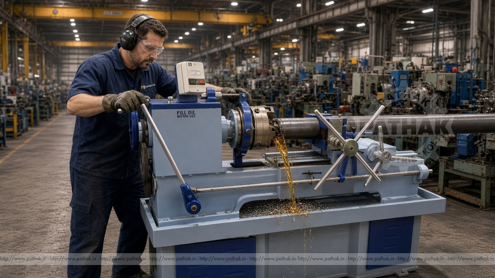
A die head threading machine cuts an external thread on a supported cylindrical workpiece. The die head holds thread-cutting chasers arranged around the material. As the work and tooling engage according to the machine design, the chasers remove material to generate the required thread form and pitch.
The machine provides controlled rotation, guided tool movement, work support, and a repeatable operating station. It may be used for suitable rods, pipes, bolts, foundation bolts, scaffolding components, and other parts requiring external threads within the selected model’s capacity.
The term “die head” is important. This equipment is not simply a general-purpose cutting machine with an ordinary fixed die. The head and its chasers must match the required thread, while the machine, workholding, and saddle movement support a planned production cycle.
The workpiece is first prepared to the correct starting diameter and end condition. It is then located and clamped so the threading axis remains aligned with the die head. The appropriate chasers are installed and adjusted for the required thread form, pitch, and size.
During the cycle, rotation and relative feed cause the chasers to cut a helical profile along the work. Cutting fluid helps cool and lubricate the tool-work interface while carrying chips away. At the planned thread length, the die head or process arrangement releases according to its approved operating method, allowing the tool to clear the newly formed thread.
The finished part is cleaned and inspected. Thread quality cannot be judged from appearance alone; suitable gauges and dimensional checks should confirm the functional size and form. Any adjustment should be based on measured results rather than arbitrary changes to several machine settings at once.
The LTM-25 is the smallest listed configuration. Its threading capacity is ¼ inch to 1 inch, saddle movement is 10 inches, and spindle speed is offered through two settings over a published 75–140 range. Production is listed at 60–80 pieces per hour, required power at 3 HP, and approximate machine weight at 900 kg.
LTM-40 extends the threading capacity from ⅜ inch to 1½ inches. It has 13 inches of saddle movement and the same published two-speed, 75–140 spindle range as LTM-25. Listed production remains 60–80 pieces per hour, with 3 HP power and an approximate weight of 1200 kg.
LTM-65 covers the largest published size range, from ½ inch to 2½ inches. Saddle movement increases to 22 inches. Its two spindle speeds are listed over a 45–90 range, production is stated at 70–90 pieces per hour, required power is 7.5 HP, and approximate weight is 1800 kg.
An optional lead screw is identified for all three models. The listed production figures are useful for comparison but should not be treated as guaranteed output for every component. Actual rate depends on thread size and length, material, blank preparation, chasers, loading, inspection, operator method, and workflow around the machine.
A machine should be chosen around the required thread family, not simply the largest available capacity. Record the major diameter, pitch or threads per inch, thread form, length, material, starting diameter, end preparation, quantity, and inspection standard for representative jobs.
A diameter that fits within a published range may still require specific chasers, work supports, spindle speed, or a thread form outside the intended tooling package. Long threaded sections also need sufficient saddle movement and stable support. If a shop handles several thread families, every one should be included in the selection review.
LTM-25 may suit smaller rods, bolts, and pipe-related work; LTM-40 provides a broader diameter range; and LTM-65 addresses larger external threads with greater saddle movement and power. Final suitability should be confirmed against actual drawings and samples.
Thread quality begins before the die head touches the part. The blank diameter and roundness should suit the required thread and cutting method. Heavy scale, burrs, damage, or an inconsistent surface can affect tool engagement and finished geometry.
The leading end normally needs an appropriate chamfer or preparation so the chasers can enter progressively. An abrupt or damaged edge may encourage poor starting, excessive load, or tool damage. The workpiece must also be straight enough for safe rotation and consistent alignment.
Cleanliness matters. Abrasive contamination can damage chasers and work supports, while residual coatings may affect cutting behavior or create unsuitable fumes. Preparation requirements should follow the material, thread standard, and established process sheet.
Chasers contain the cutting geometry that forms the thread. They must match the required thread system, pitch, size range, and die head. A set should be installed in its correct positions and adjusted according to the tooling procedure.
Worn, chipped, mixed, or incorrectly ground chasers can produce poor form, rough flanks, taper, oversize or undersize threads, and excessive cutting load. Chasers should be stored as identified sets and inspected before use. Regrinding, where applicable, must preserve the required geometry.
The die head should open, close, and locate consistently. Chip accumulation or wear in its mechanism can affect release and adjustment. Operators should never force a head that does not move as expected; the machine should be stopped and the cause investigated.
The product is associated with bolt threading, foundation-bolt threading, pipe threading, scaffolding-pipe threading, rebar threading, and suitable PVC pipe threading. These operations appear in fastener plants, fabrication shops, pipe-processing facilities, scaffolding production, construction-component manufacturing, and maintenance departments.
Foundation bolts may require repeated threads over a defined length for structural installation. Scaffolding components need threads that assemble reliably with compatible fittings. Fastener production demands consistent gauge acceptance across batches. Pipe work requires the thread type and preparation to match the intended joint and material.
These examples should not be grouped under a single setup merely because each involves a thread. Material behavior, thread form, blank geometry, workholding, tooling, cutting fluid, and inspection can differ significantly. Each part family needs its own approved process.
The published machines provide two spindle speeds within model-specific ranges. LTM-25 and LTM-40 are listed at 75–140, while LTM-65 is listed at 45–90. The appropriate selection depends on diameter, material, chasers, thread form, and cutting conditions.
Higher speed does not automatically produce better output. An unsuitable speed can increase heat, tool wear, chip problems, or finish defects. Feed must remain coordinated with the required thread lead through the die-head process and machine arrangement.
Cutting fluid supports lubrication, cooling, and chip removal. The correct fluid and delivery depend on material and tooling guidance. Flow should reach the cutting zone without creating uncontrolled splash, while the fluid system requires filtration and routine care to prevent recirculating chips through the tool.
A finished external thread should be inspected using methods appropriate to its specification. Go/no-go ring gauges can provide a functional acceptance check for a defined thread. Additional measurement may be needed for major diameter, pitch diameter, thread length, lead, form, or surface condition.
Inspect the first component after setup before committing an entire batch. Continue checks at planned intervals because tool wear, workpiece variation, heat, and adjustment can shift the process. Inspection frequency should reflect production stability and the importance of the threaded connection.
If a thread fails inspection, determine whether the cause is blank size, alignment, chaser setting, tool wear, speed, fluid, workholding, or another process condition. Correcting the true cause is more reliable than compensating blindly at the die head.
The specification lists hourly production ranges, but practical output includes more than cutting time. Material must be staged, loaded, aligned, clamped, threaded, unloaded, cleaned, inspected, and transferred. Long or heavy workpieces may need handling assistance and additional support.
A balanced cell keeps prepared blanks, gauges, chasers, cutting fluid, and finished-part containers organized around the machine. Standard work instructions can document loading orientation, tool settings, thread length, speed, inspection frequency, and reaction to a nonconforming part.
Productivity should not be improved by skipping inspection or safe handling. A rapid cycle that creates damaged chasers, rejected threads, or unsafe loading is not an efficient process.
Use LTM-25, LTM-40, and LTM-65 capacity ranges as the first filter. Then compare required threaded length with saddle movement, the material and diameter with available spindle speeds and power, and the part-handling method with machine size and approximate weight.
Review current and likely future jobs without oversizing the machine blindly. A larger model may cover greater diameters but uses a different speed range, power level, and installation arrangement. Conversely, selecting only for today’s smallest component can restrict future work.
Provide Pathak Industries with drawings, samples, thread standards, materials, batch quantities, maximum lengths, and inspection needs. Confirm chaser and die-head availability for every required thread before finalizing the purchase.
Rotating rods and pipes create entanglement and impact hazards, especially when they project beyond the machine. Long stock requires approved supports and guarding. Loose clothing, gloves near rotation, jewelry, hair, and unsecured tools must be controlled according to workshop procedure.
Guards should remain in position, and the operator should keep clear of the rotating work, die head, saddle, and chips. Stop the machine before measuring, clearing chips, changing chasers, adjusting supports, or investigating a problem. Use appropriate tools for chip removal rather than hands.
Cutting fluid, electrical equipment, floors, lifting, and material storage also require attention. Only trained personnel should operate or service the machine, and all energy should be isolated before maintenance.
Keep the machine clean and lubricated according to its maintenance schedule. Inspect the spindle, die head, saddle, slides, workholding, supports, drive, guards, controls, and fluid system. Chips should not be allowed to pack into the die-head mechanism or slideways.
Monitor chaser condition and keep sets identified. Check cutting-fluid concentration and cleanliness where applicable, clean filters and tanks, and investigate leakage. Fasteners, electrical connections, and optional lead-screw components should receive the documented checks.
Changes in noise, vibration, temperature, finish, chip form, or gauge results can indicate developing problems. Recording maintenance and inspection findings helps identify changes before they interrupt a batch.
It cuts external threads on suitable rods, pipes, bolts, construction components, and related cylindrical workpieces using a die head fitted with matching chasers.
LTM-25 is listed from ¼ to 1 inch, LTM-40 from ⅜ to 1½ inches, and LTM-65 from ½ to 2½ inches.
Each model has two listed spindle speeds. The published ranges are 75–140 for LTM-25 and LTM-40, and 45–90 for LTM-65.
These are recorded applications for the product, provided the diameter, material, thread form, length, tooling, support, and selected model suit the actual component.
Correct end preparation helps the chasers start progressively and concentrically. A damaged, square, or poorly prepared edge can increase load and create an unacceptable thread start.
Use gauges and measurements specified for the required thread. A go/no-go ring gauge may provide a functional check, while critical jobs can require additional diameter, pitch, lead, form, or length inspection.
Provide thread diameter and standard, pitch, thread length, workpiece material and length, starting blank condition, batch quantity, required output, inspection method, and available utilities.
A die head threading machine turns external-thread production into a defined sequence of blank preparation, workholding, guided cutting, fluid delivery, release, and inspection. The LTM-25, LTM-40, and LTM-65 configurations allow workshops to select different capacity, travel, speed, power, and production ranges.
Reliable output comes from matching the model and chasers to the real thread, preparing each blank correctly, maintaining alignment and fluid, inspecting parts throughout the batch, and caring for the die head. When those controls are in place, the machine can support efficient production of consistent threaded components across fabrication and industrial applications.