Head Office
117, Grand Trunk Road, Salkia Howrah-700013, Kolkata, India
 Hitesh PathakFri, Nov 1, 2024
Worn bores can create looseness, misalignment, uneven loading, and unreliable movement in heavy equipment and industrial assemblies. Repairing them conventionally may require dismantling a large component and transporting it to a fixed machine shop. Portable line boring offers another approach: the machining equipment is mounted around the bore so the damaged feature can be restored at the component or worksite.
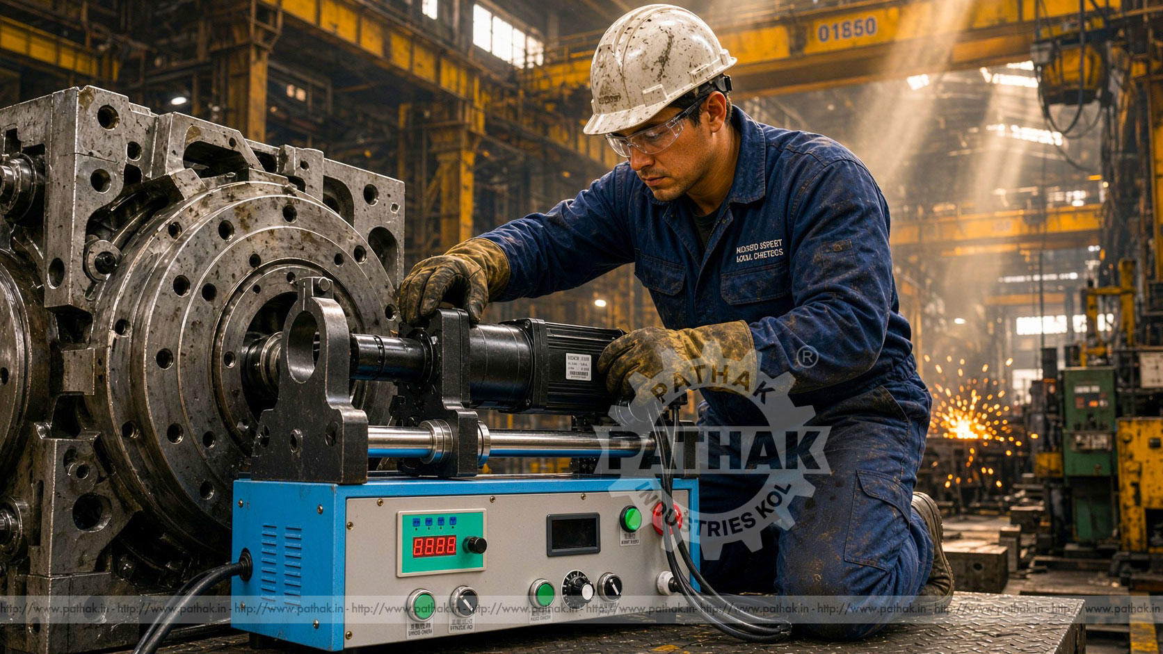
The Indiborer Mini Yantra from Pathak Industries is a compact portable line-boring system with a published working range of 45–200 mm. It combines a boring bar, drive system, adjustable speed and feed, and screw-supported mounting arrangement for suitable field and workshop repairs. This guide explains its operating principle, documented specifications, setup sequence, applications, selection factors, and maintenance requirements.
The Indiborer Mini Yantra is a portable machine for machining cylindrical bores in components that may be difficult or uneconomical to place on a conventional boring machine. Instead of moving the complete workpiece to a stationary machine tool, the boring bar and drive are aligned with the existing bore and supported at the job.
A cutting tool mounted in the rotating bar removes material from the bore as a controlled feed moves it through the work. The objective may be to restore roundness, correct alignment between related bores, enlarge a worn feature to a repair size, or prepare the bore for a sleeve or bush. The exact repair method depends on the component, wear condition, material, available stock, and engineering requirement.
The “Mini Yantra” designation reflects a compact format, but compact does not mean that setup can be casual. Portable machining depends heavily on mounting rigidity, bore alignment, bearing-support position, bar condition, tool setting, and measured verification.
Line boring establishes a machining axis through one or more related bores. Support bearings hold the boring bar around the job, and an alignment process positions that bar according to the intended bore centerline. The drive rotates the bar while a feed system advances the cutting tool through the work.
Before machining, the repair team examines the component and determines how the finished axis will be established. Existing unworn reference surfaces, related bores, drawings, measurements, or an approved repair procedure may be used. The supports are then attached securely, and the bar is checked through its movement to confirm clearance and alignment.
The tool is set for a controlled cut. Material is normally removed in planned passes rather than attempting the entire correction at once. Measurements between passes show whether diameter, roundness, and alignment are developing as intended. The final strategy may include a finishing pass and subsequent sleeving, depending on the repair design.
The Indiborer Mini Yantra has a listed boring-hole diameter range of 45–200 mm. The same 45–200 mm range is published for milling. Boring-bar lengths of 1500 mm and 2000 mm are available in the product data, providing alternatives for different working reaches and support arrangements.
Spindle movement is listed at 290 mm, and the maximum turning amount is 2 mm. The drive system is specified as a servo motor or brushless motor with 1.8 kW power and published torque of 61 N·m. Spindle speed is adjustable from 0 to 200 RPM, while the feed-speed range is listed from 0 to 90 mm/min. The technical table also records a feed-rate value of 6 mm/rpm; its application to a proposed process should be confirmed from the current operating documentation.
Power supply is listed at 220 V. The published performance figures include 3.2 Ra surface roughness and 0.02 mm boring roundness error. These figures describe the product data, but actual repair results remain dependent on setup rigidity, alignment, tool condition, material, cut selection, support spacing, measurement, and operator practice.
Portable line boring is relevant wherever a worn bore exists in a component that is large, installed, heavy, or inconvenient to move. Common environments include construction-equipment repair, mining maintenance, fabrication yards, industrial plants, agricultural-equipment service, material-handling maintenance, and heavy engineering workshops.
Possible work includes pin bores, pivot points, hinge locations, bearing housings, coupling features, structural bores, and aligned bore sets. Each job must fall within the machine’s working range and provide a safe, rigid method for mounting the supports and drive.
On-site machining can reduce the dismantling and transport associated with fixed-shop repair. It can also allow alignment to be established relative to the assembled structure. Those benefits depend on site access, cleanliness, power, lifting arrangements, safe working space, and protection of nearby equipment.
A repair should begin with inspection rather than immediate cutting. Clean the bore and surrounding area, then measure diameter at several positions and directions. This helps identify ovality, taper, bell-mouth wear, scoring, previous repair material, or a shift in alignment. Related pins, bushes, bearings, and mating parts should also be inspected.
The team must decide the intended finished condition. A bore may be machined directly to a specified diameter, opened for a replacement bush, or prepared for another approved restoration process. The amount of remaining parent material and the structural condition of the component must support that decision.
If several bores share an axis, all relevant locations should be considered during alignment. Correcting one bore independently can leave the assembly with a different alignment problem. Measurements and the repair plan should therefore define the complete functional relationship.
The boring bar must be supported rigidly while remaining free to rotate and feed. The product lists a screw-type support structure. Supports should be positioned to control deflection and provide access to the cutting area without interfering with the tool path, drive, or measurement.
Alignment may involve centering devices, measured offsets, test indicators, reference bores, or other approved methods. Adjustments are made until the bar represents the required finished axis. The bar should then be rotated or moved through its intended path to confirm that alignment remains stable and nothing binds.
Mounting points must withstand machining forces. Temporary brackets or attachments require appropriate engineering and workmanship. A support that moves during a cut can affect diameter, finish, roundness, and safety.
The cutting tool projects from the boring bar and must be set according to the required diameter. Tool geometry should suit the workpiece material and operation. Excessive projection can reduce rigidity, while insufficient clearance can cause rubbing or chip congestion.
Spindle speed and feed should be selected within the documented ranges according to bore diameter, material, tool, support stability, depth of cut, and finish requirement. A trial or roughing pass can reveal how the setup behaves before the final dimension is approached.
Measure after suitable passes and account for temperature, surface condition, and instrument access. As the finished size approaches, smaller controlled adjustments can reduce the risk of removing too much material. If the repair uses a bush, the specified fit and the bush’s finished internal dimension must both be part of the machining plan.
A long boring bar can deflect or vibrate when its support arrangement is inadequate. Bar length, unsupported span, cutter position, depth of cut, speed, feed, and material all influence cutting behavior. The available 1500 mm and 2000 mm bars should therefore be selected and supported for the actual job rather than used interchangeably without evaluation.
Chatter may leave a poor finish and make diameter control difficult. The response is not automatically to increase cutting load. The operator should review support spacing, bearing condition, alignment, tool sharpness, projection, speed, feed, and mounting rigidity.
Stable support also protects the relationship between multiple bores. If the bar changes position as the cutter moves from one support region to another, aligned features may not share the intended axis.
The central benefit of portable line boring is that machining can be taken to the component. For suitable repairs, this may reduce complete disassembly, transport, crane use, and time away from service. The equipment can also be mounted relative to the actual structure, which is useful when bore alignment depends on assembled geometry.
Portable machining does not eliminate repair engineering. The component must be structurally repairable, the mounting method must be safe, and the final bore must be inspected against the required dimensions and alignment.
Compare the smallest starting bore, required finished diameter, total machining length, distance between support locations, access around the component, and required bar reach with the published machine range. Review material, available power, repair location, lifting needs, environmental conditions, and how chips will be contained.
The 45–200 mm range establishes a useful starting point, but a diameter alone does not prove suitability. A bore near a restricted wall, deep within a structure, or surrounded by obstacles may require a different mounting approach from an open housing of the same diameter.
Provide drawings, photographs, measured wear, bore spacing, material information, required finished size, tolerance, and site constraints when discussing the application with Pathak Industries. This makes it possible to review bar length, supports, tooling, drive choice, and practical access together.
Portable machines are often used in non-standard locations, so the work area must be controlled carefully. Isolate the parent equipment and verify that no connected mechanism can move. Secure the boring equipment, cables, supports, and work zone against interference from other site activity.
Rotating bars, exposed tools, chips, sharp edges, and unexpected tool breakthrough create hazards. Guards and exclusion zones should be used where applicable. Keep hands, clothing, measuring instruments, and loose objects away from rotating components. Stop and isolate the system before adjusting the tool, supports, or alignment.
Site procedures should address electrical supply, work at height, confined access, lifting, hot work near mounting brackets, and protection from weather or contaminants where relevant. Only trained personnel should operate or service the equipment.
Clean the boring bar, support bearings, drive, feed assembly, and tooling after use. Inspect bar surfaces for damage, keep mounting threads and adjustment points serviceable, and protect precision parts during transport and storage. A dented, corroded, or contaminated bar surface can affect support movement and alignment.
Check electrical connections, drive condition, fasteners, cables, controls, and lubrication according to the supplied schedule. Cutting tools should be sharpened or replaced before wear produces excessive load or poor finish. Measuring equipment used for setup and inspection should remain suitable and verified.
Before a critical repair, confirm bar condition and system operation through the documented checks. Maintenance records are especially useful for portable equipment because it may travel between demanding sites and different operating teams.
It is used for portable line boring of suitable worn, oval, oversized, or misaligned bores. The machine is mounted around the component so the bore can be restored in a workshop or at the equipment location.
The published boring-hole range is 45–200 mm. The product data also lists the same 45–200 mm range for milling.
The technical specification lists 1500 mm and 2000 mm boring bars. Selection depends on working reach, support locations, bore spacing, access, and the rigidity required by the job.
The published spindle-speed range is 0–200 RPM. The operating speed should be selected for bore diameter, material, tool, cut, feed, and support stability.
A line-boring setup can machine related bores around a common bar axis when the machine range, bar length, support arrangement, and component access suit the job.
The product data lists 220 V supply and a 1.8 kW servo or brushless-motor drive. Current electrical and installation details should be confirmed before site preparation.
Provide starting and finished bore diameters, bore length and spacing, component material, measured wear, required alignment and finish, site photographs, available power, access limits, and preferred repair method.
The Indiborer Mini Yantra brings controlled boring to components that may be impractical to move to a conventional machine tool. Its published 45–200 mm range, bar-length options, variable drive, and controlled feed provide a technical foundation for appropriate workshop and field repairs.
Successful line boring depends on far more than rotating a bar through a worn hole. Inspection, repair planning, rigid mounting, accurate alignment, thoughtful support placement, controlled tool setting, and dimensional verification must work together. When those stages are managed carefully, portable machining can restore functional bore geometry while reducing unnecessary component movement and downtime.