Head Office
117, Grand Trunk Road, Salkia Howrah-700013, Kolkata, India
 Hitesh PathakFri, Oct 11, 2024
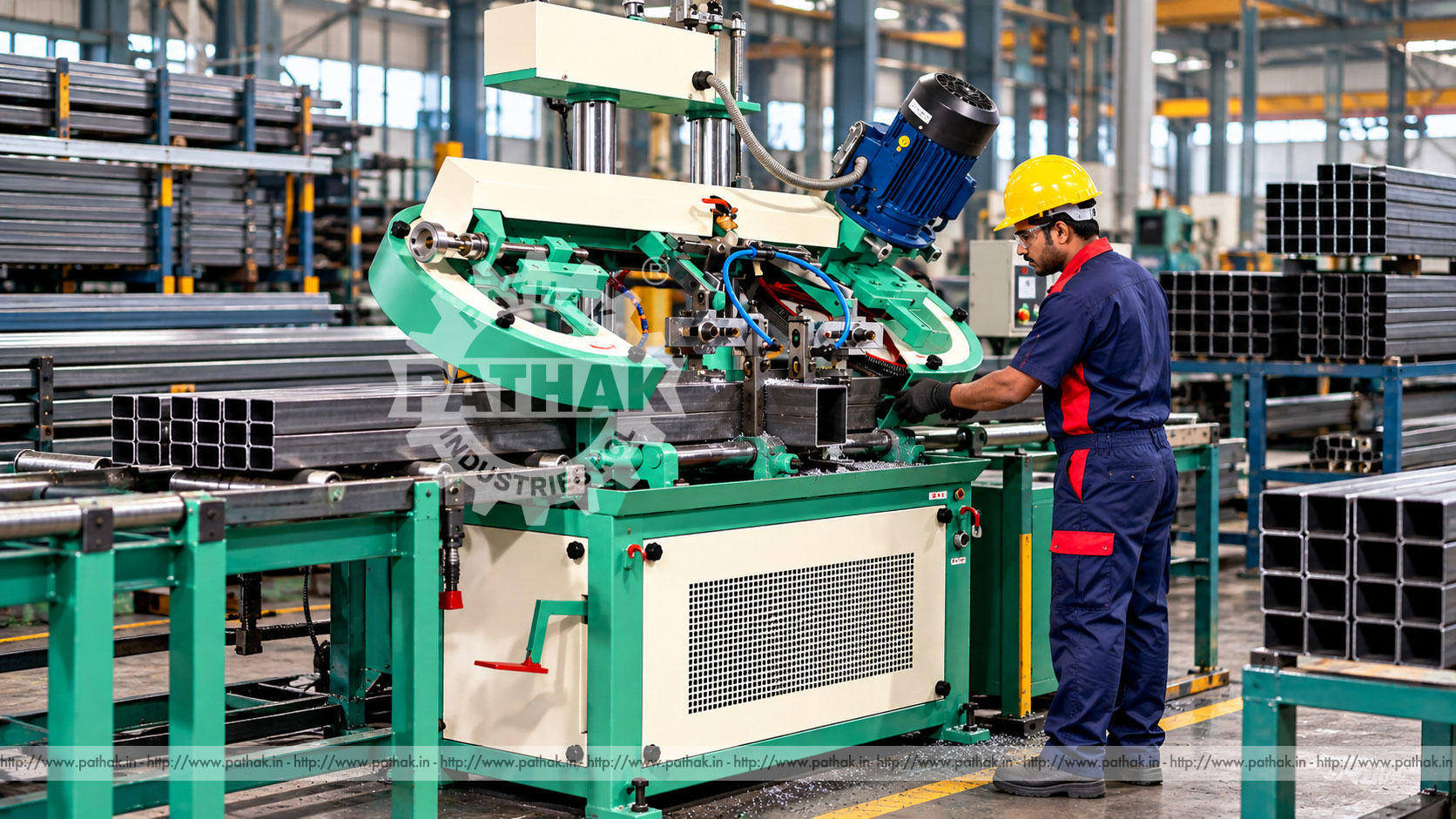
Cutting solid bars, square stock, tubes, and bundled material into controlled lengths is a critical first stage in fabrication and machining. Poor cut quality can add facing time, waste material, and disrupt every downstream operation. The Horizontal Double Column Bandsaw Machine Model-200 F.A. combines a rigid two-column guiding arrangement with hydraulic cutting control for repeat stock preparation.
The Pathak Industries 200 F.A. lists 200 mm capacity for round bars, 200 × 200 mm for square stock, and 200 × 200 mm for bunch cutting. It uses a 27 × 0.9 × 3200 mm blade with selectable speeds of 32, 44, and 56 m/min. A dedicated coolant pump and hydraulic drive support the cutting cycle, while the machine’s listed net weight is 625 kg.
A horizontal bandsaw moves a continuous loop blade through stock held along a level machine axis. Blade teeth remove a narrow kerf as the saw head descends. The double-column layout guides the moving saw structure at two separated points, helping it remain stable across the cutting width.
This arrangement is useful for production cutting where section size, squareness, repeatability, and blade guidance matter. Actual results still depend on blade selection, tension, feed pressure, vise clamping, coolant, stock support, and material condition.
Stock is loaded onto the machine bed or roller supports and positioned to the required cut length. The vise secures it against movement. Once guards, blade condition, and settings are confirmed, the blade starts and the hydraulic system controls head descent through the material.
Coolant reaches the tooth-work interface to limit heat, lubricate the cut, and help remove chips. At completion, the head returns according to the machine’s operating arrangement. The cut piece is removed only when movement has safely stopped.
The Model 200 F.A. is rated for 200 mm round bar and 200 × 200 mm square stock. Its bunch-cutting capacity is also listed as 200 × 200 mm. Capacity describes the machine opening under the stated configuration, but a workpiece must also be clamped securely and supported throughout the cut.
Irregular profiles, thin-wall tubes, nested sections, and loosely bundled stock require special attention. A nominal bundle fitting inside 200 × 200 mm may still move if individual pieces are not contained by the clamping arrangement.
Two columns guide the saw-head movement across the work area. This geometry helps resist twisting forces produced as the blade enters and exits different parts of the section. Stable guidance supports straighter cuts when the rest of the setup is correct.
Column surfaces, guide components, and moving connections must remain clean and correctly lubricated. Chips packed into guides or damaged alignment components can reduce the benefit of the double-column structure.
The published blade size is 27 mm wide, 0.9 mm thick, and 3200 mm long. A replacement blade must match these dimensions and the wheel and guide arrangement. Tooth pitch and tooth form then need to match the stock.
Solid sections generally require a tooth pitch that keeps several teeth engaged without overloading the gullets. Thin-wall tubes and profiles need enough teeth in contact to avoid snagging. Variable-pitch blades can help reduce repetitive vibration in suitable work, but the precise blade should be selected from the actual material and section.
The 200 F.A. lists blade speeds of 32, 44, and 56 metres per minute. These choices allow the operator to match cutting speed more closely to material machinability, diameter, blade, and coolant conditions.
Hard or difficult material often needs a lower speed than readily machinable stock. Excessive speed can shorten tooth life and create heat, while unnecessarily low speed can reduce output. The approved blade recommendation and observed chip condition should guide selection.
Cutting-speed control is listed as power hydraulic, supported by a 1 HP, 1500 rpm hydraulic drive motor. The hydraulic system regulates head movement and the blade’s engagement with the work.
Feed must allow the teeth to cut rather than rub or overload. Too much pressure can cause blade deviation, tooth damage, or motor load. Too little can create rubbing and premature dulling. Hydraulic oil level, filters, seals, valves, hoses, pressure, and temperature require regular attention.
The main motor is listed at 0.85 HP and 960 rpm. Coolant is supplied by a dedicated 0.15 HP, 2800 rpm pump. These systems should be checked before a production run, particularly after extended idle periods.
Coolant concentration and condition affect lubrication, corrosion control, and tool life. The tank and delivery points should remain free of excessive chips. A weak or misdirected flow can leave one side of the blade without adequate cooling.
Round bar should sit securely in the vise without rolling. Square stock needs clean seating against the fixed jaw. Tubes and hollow structural sections can present changing tooth engagement as the blade passes through walls and open spaces.
Sharp corners, weld seams, scale, and interrupted bundles affect cutting load. The operator should position profiles consistently and choose a blade that can tolerate the section. Unsupported long stock can lever against the vise and distort the cut.
The listed 200 × 200 mm bunch capacity allows multiple compatible pieces to be cut in one cycle. Bundle cutting can improve throughput when each item has the same cut requirement and the pack is safely constrained.
All pieces must remain immobile. Round bars may need top clamping or containment to prevent rotation. Gaps and uneven stacking can cause the blade to enter material unpredictably. A trial bundle should be inspected before the process is released for quantity production.
Long bars and sections need aligned infeed and outfeed supports at machine-bed height. Roller tables can reduce manual lifting and prevent stock from sagging. Stops or measuring systems help establish repeat cut length.
The 200 F.A. machine dimensions are listed as 1500 × 1900 × 1750 mm. Factory planning must add space for stock length, offcuts, controls, coolant service, blade changes, maintenance, and safe movement of people and handling equipment.
Chips provide useful feedback. Very fine powder may indicate rubbing or insufficient feed, while thick discoloured chips may indicate excessive load or heat. Chip shape varies by material and blade, so operators should learn the acceptable range for each approved process.
A cut that runs out of square can result from worn teeth, uneven tooth set, insufficient tension, guide misalignment, excessive feed, loose clamping, or unsupported stock. Correcting only the feed may not solve an underlying mechanical issue.
The Model 200 F.A. can support steel stockholders, fabrication shops, machine shops, maintenance departments, tube and profile processing, component plants, and production cells requiring blanks up to its confirmed capacity.
Material suitability should be established with the correct blade and parameters. The product page broadly references different stock types, but this model’s final application should be confirmed from samples, material specification, and required output.
The double-column structure supports controlled vertical movement across the cutting area.
Published capacities cover round, square, and bundled material up to 200 mm or 200 × 200 mm.
Three speed choices allow better matching to different approved materials and sections.
Powered hydraulic descent provides a controllable approach to repeat cutting cycles.
The continuous blade, hydraulic head, vises, stock, and falling offcuts create cutting and crushing hazards. Guards must remain fitted, and hands must stay outside the cutting and clamping zones. Stock should be loaded with suitable equipment.
The saw must be isolated before blade changes, guide adjustment, chip removal near hazards, clearing jams, or maintenance. Stored hydraulic energy must be released safely. Gloves should only be used according to site rules and never where they could contact moving machinery.
Daily checks cover blade teeth and tracking, tension, guides, vise operation, coolant level and flow, hydraulic leakage, guards, switches, and emergency controls. Chips should be removed from the bed and collection areas without forcing them into moving components.
Scheduled maintenance should include blade wheels, bearings, guides, drive components, hydraulic oil and filters, coolant tank, pump, electrical connections, column alignment, fasteners, and foundation. Maintenance history helps distinguish normal blade wear from a developing machine problem.
Provide maximum round and rectangular sizes, material grades, hollow-wall thicknesses, bundle arrangement, cut length, tolerance, finish, daily quantity, and stock length. Confirm capacity, blade, speeds, vise, feed, coolant, and handling layout against representative jobs.
The smaller 125 F.A. may suit lighter work, while the 200 F.A. provides the listed 200 mm class capacity. Selection should reflect sustained production needs, not only the largest part encountered occasionally.
The Model 200 F.A. is listed for round bar up to 200 mm.
Both square-stock and bunch-cutting capacity are listed at 200 × 200 mm.
The published blade size is 27 × 0.9 × 3200 mm. Tooth selection depends on material and section.
The listed options are 32, 44, and 56 metres per minute.
The machine uses power-hydraulic cutting control with a listed 1 HP hydraulic drive motor.
Yes. The product data lists a dedicated 0.15 HP coolant pump.
Overall dimensions are listed as 1500 × 1900 × 1750 mm, and net weight is 625 kg.
Provide stock shapes and sizes, material grades, bundle details, tolerances, daily output, length range, available floor space, utilities, and handling requirements.
The Pathak Industries Horizontal Double Column Bandsaw Model 200 F.A. provides 200 mm-class capacity, stable two-column guidance, three blade speeds, hydraulic feed control, and dedicated coolant for repeat stock preparation. Correct blade selection, secure clamping, aligned supports, controlled feed, inspection, and preventive maintenance are essential to realise that capability safely and economically.