Head Office
117, Grand Trunk Road, Salkia Howrah-700013, Kolkata, India
 Hitesh PathakWed, Jun 16, 2021
Permanent identification on cylindrical components helps manufacturers communicate part numbers, sizes, grades, ownership, traceability codes and brand identity. An Engraving Branding Lathe Machine supports this work by rotating the component while a controlled tool produces repeated marks around or along its surface.
The process may be applied to rollers, shafts, dies, cylinders, sleeves, rings and other rotational parts whose marking pattern must follow a controlled position. This guide explains the operating principle, common applications, tooling, setup, quality control, safety, maintenance and the information to review before selecting a machine.
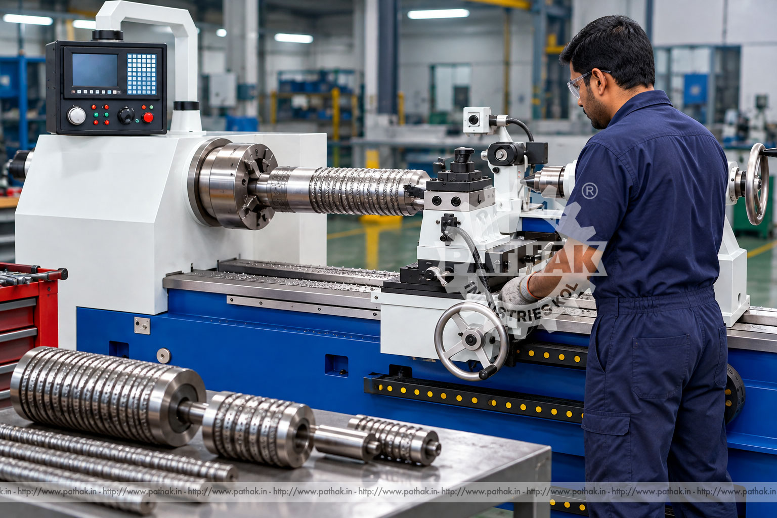
An engraving branding lathe machine is a specialised turning-platform machine used to create permanent characters, logos, numbers, symbols, textures or identification patterns on a rotational workpiece. The part is held between a chuck, centres or another suitable fixture and rotated at a controlled speed. A marking or cutting tool is then positioned relative to the surface.
Depending on the tooling and control arrangement, the machine may produce circumferential bands, indexed marks, repeated characters, helical layouts or longitudinal engraving. The exact capability depends on the machine configuration, control system, axes, spindle synchronisation, tooling and workpiece geometry. Buyers should confirm the required pattern from a drawing or approved sample.
Industrial components can pass through machining, heat treatment, assembly, inspection, dispatch and years of service. Labels and paint may be damaged or removed during these stages. A correctly specified engraved mark becomes part of the component surface and can remain readable under demanding handling conditions.
Common purposes include:
The marking content, depth and location should be controlled by the applicable drawing, customer standard and quality plan. Critical parts may restrict where material can be removed or displaced.
The operator first centres and clamps the workpiece so it runs true. The tool is aligned to the required marking position and the spindle is set to a suitable speed. Relative motion between the rotating component and the tool creates the desired form.
For a simple circumferential mark, the tool can remain at a fixed axial position while the work rotates. A pattern extending along the component requires coordinated carriage movement. Indexed branding may require the spindle to stop or advance to repeatable angular positions. Computer-controlled variants can coordinate spindle rotation and tool movement from a prepared program.
Mark quality is influenced by workpiece runout, surface finish, tool condition, depth of cut or forming pressure, feed, spindle speed, rigidity, material hardness and the accuracy of the pattern data.
The terms engraving and branding can describe several processes. The correct method depends on the material and the required appearance.
A sharp tool removes a controlled amount of material to create recessed lines or characters. Cut engraving can produce defined edges and variable depths, but it creates chips and must not reduce the component section beyond the approved limit.
A hardened tool displaces rather than removes surface material. This can reduce swarf, although the process creates local forming forces and raised edges that may require evaluation.
Repeated grooves, symbols or surface textures may be applied to rollers and dies used in later manufacturing operations. In such applications, pattern pitch, depth, phase and continuity can be as important as the visual appearance.
Letters, numbers or logos are placed at controlled angular positions. Accurate indexing and secure workholding are necessary to maintain spacing and orientation.
An engraving branding lathe machine may include:
Actual features vary by model. Confirm work capacity, spindle bore, swing, distance between centres, speed range, supported axes and software functions from the current technical offer.
The machine may be considered for suitable:
Suitability depends on the component material, hardness, wall thickness, diameter, length, balance, surface condition and permitted marking zone.
Clean the marking area before setup. Oil, paint, scale, rust and loose contamination can interfere with tool contact and visibility. If the part requires prior turning or grinding, complete enough preparation to establish a consistent reference surface.
Inspect the part for distortion, cracks, severe runout and damaged centres. Thin-walled work needs particular care because excessive chuck force, support pressure or engraving load can deform it. Confirm that marking will not cross a sealing surface, bearing seat, highly stressed radius or another prohibited feature.
Workholding must resist both rotational torque and the cutting or forming force. Chuck jaws, centres, mandrels and fixtures should contact approved surfaces without damaging finished features. Long components may need a tailstock, steady rest or additional support.
Indicate the workpiece before marking. Excessive runout changes engraving depth around the circumference and can cause incomplete or heavy sections. For patterns that must align with an existing keyway, hole or datum, establish the angular reference before starting the program or indexing cycle.
Tool material and geometry must suit the workpiece material, hardness, mark style and depth. A fine cutting tip may produce detailed characters but can be fragile. A larger radius is stronger but may not reproduce small features. Forming tools require sufficient hardness and a profile that produces the desired impression without uncontrolled cracking or raised material.
Tool overhang should be kept as short as practical. Inspect the cutting edge or marking point under suitable magnification. Wear, chipping or built-up material can change line width and depth even when the program remains unchanged.
Where the machine uses numerical control, begin with approved artwork or text. Convert logos into clean paths and remove overlapping, duplicate or unnecessary geometry. Very small gaps and sharp corners may be unsuitable for the selected tool size.
Confirm:
Run a simulation or air cycle where available. A sample on comparable material is advisable before marking an expensive finished component.
There is no single setting for every engraving job. Spindle speed, surface speed, axial feed and depth depend on tool type, material, hardness, diameter, pattern complexity and rigidity. Begin from the tooling and machine recommendations, then validate through controlled trials.
Excessive depth can overload the tool, distort fine details and create burrs. Too little depth may produce an unreadable mark after finishing or service wear. High speed can generate heat or vibration, while unsuitable low speed may create irregular cutting. Record approved settings for repeat work.
A flat drawing wraps around a curved surface. Character width and spacing must therefore be related to circumference. A full wrap requires the pattern length to match the effective circumference at the engraving diameter. Errors can create a visible gap, overlap or mismatched joint.
Helical patterns require accurate coordination between spindle rotation and axial feed. Indexed patterns require consistent angular positioning. On tapered work, the changing diameter may require specialised programming or tooling to maintain depth and spacing.
An inspection plan may check:
Use approved samples, drawings and calibrated instruments. Vision inspection may assist repeated production, but acceptance criteria should be defined before the batch begins.
Likely causes include workpiece runout, poor support, inconsistent surface condition, loose tooling, guideway play or an incorrect tool-height relationship. Check alignment before increasing depth.
Review tool overhang, work support, spindle speed, feed, machine rigidity and tool sharpness. Long or thin workpieces may need additional support.
A dull or unsuitable tool, excessive depth, incorrect speed, material pickup or poor cutting direction can damage the mark edges. Adjust only after confirming the tool and material condition.
Confirm the actual engraving diameter, circumference calculation, spindle indexing, program scaling and mechanical backlash. Do not stretch approved artwork without checking character proportions.
Establish how the mark must read when the part is installed. Verify spindle direction, artwork direction, datum and start position during first-piece approval.
Rotating work, chucks, tools and chips present entanglement, impact and cutting hazards. Operators must receive machine-specific training and follow the applicable risk assessment and operating instructions.
Daily checks should cover lubrication, guards, controls, tool condition, chuck security, guideway cleanliness and unusual noise. Keep chips away from slides, screws, sensors and electrical equipment.
Planned maintenance should inspect spindle bearings, drive components, chuck condition, tailstock alignment, guideways, feed screws, encoders, cables, control ventilation and foundation fasteners. Back up machine parameters, programs and approved artwork according to the control supplier's procedure.
Maintain a tooling record with the material, mark type, approved settings, production quantity, inspection results and observed wear. This supports repeatable changeovers and timely tool replacement.
Prepare the following information for the manufacturer:
Compare the proposed machine's swing, work length, spindle arrangement, speed range, axis travel, positioning method, tool interface, control functions, guarding and service support. Request a representative sample trial when mark quality or component value makes process confirmation important.
Depending on its tooling and controls, it can produce suitable text, serial numbers, logos, symbols, circumferential bands, indexed marks and repeated patterns on rotational components.
Potential suitability depends on the actual hardness, case depth, mark requirement, tool material and machine rigidity. Provide the material specification and request a trial for hardened work.
Any removal or displacement of material changes the local surface. Engineering approval should define the permitted location and depth, especially near stressed, sealing, bearing or fatigue-critical areas.
It may be possible when the machine and control support the required coordinated movement. Supply clean vector artwork, the marking diameter, dimensions and desired orientation for review.
Consistent depth requires low workpiece runout, rigid support, sound guideways, secure tooling, controlled tool position and a uniform surface. First-piece inspection should confirm the setup.
A helical pattern requires controlled coordination between workpiece rotation and axial tool movement. Confirm this capability, pitch range and programming method for the proposed model.
A clean vector file is generally preferable because paths can be scaled and checked. Also provide a dimensioned drawing defining the marking diameter, position, size, depth and readable orientation.
Send component drawings, material and hardness, size and weight range, artwork, mark depth and tolerance, batch quantities, workholding needs, inspection criteria, utilities and installation details.
An Engraving Branding Lathe Machine provides a controlled way to place permanent identification or functional patterns on suitable cylindrical components. Reliable results come from accurate workholding, low runout, appropriate tooling, validated speed and feed, clean program data, first-piece approval and disciplined inspection.
Selection should begin with the actual components and required marks. Confirm capacity, control functions, tooling, fixture design, quality criteria, guarding and service support against the current machine offer before finalising a configuration.