Head Office
117, Grand Trunk Road, Salkia Howrah-700013, Kolkata, India
 Hitesh PathakWed, Jan 7, 2026
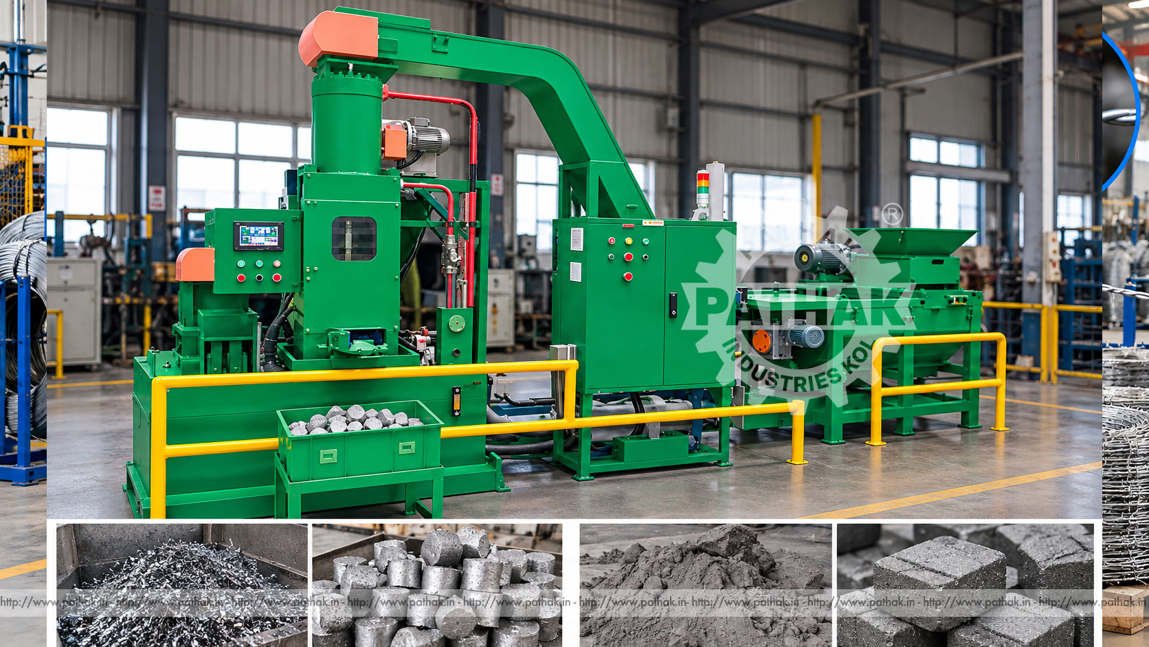
Machining operations generate loose chips that occupy storage space, retain cutting fluid, scatter during handling, and complicate transport. A Chip Compactor Machine applies high hydraulic force to prepared metal chips, forming dense briquettes that are easier to collect, store, move, and send into an approved recovery route.
Pathak Industries lists two configurations: PCC12-110 and PCC12-150. Both produce a listed 100 × 50 mm briquette, use a 15 HP electric motor, and have a stated 23-second cycle. Their primary difference is hydraulic force: 110 tons for PCC12-110 and 150 tons for PCC12-150. The correct model depends on chip material, shape, bulk density, fluid content, required briquette condition, and production volume.
A chip compactor, also called a chip briquetting machine in this context, compresses loose machining residue inside a controlled chamber. Hydraulic pressure reduces void space and forms a repeatable solid shape. The briquette can simplify material handling compared with loose swarf.
This machine is different from a vibrating soil compactor. Although the current product page contains generic text about ground compaction, its technical table clearly describes hydraulic force, briquette size, cycle time, and industrial machine dimensions. This guide therefore follows the verified briquetting specification.
Prepared chips enter the feed system or compaction chamber according to the machine arrangement. A measured charge is confined, and the hydraulic ram applies the selected forming force. Pressure compacts the chips into the 100 × 50 mm listed briquette format.
After compaction, the ram returns and the formed briquette is ejected or transferred to collection. The published cycle time is 23 seconds for both models. Actual hourly output also depends on feeding consistency, chip characteristics, interruptions, briquette handling, and maintenance.
The PCC12-110 supplies 110 tons of listed hydraulic force and measures 1700 × 900 × 2200 mm. The PCC12-150 supplies 150 tons and measures 1700 × 900 × 2500 mm. Both use a 15 HP electric motor.
Higher force may be useful for a material or briquette target that needs greater compression, but force alone should not decide the purchase. Representative chip trials help establish whether the material feeds reliably and whether the resulting briquette has the required handling integrity.
The listed briquette size provides a consistent output form for collection and storage. Finished density and mass are not stated on the product page and should not be assumed, because they vary with metal type, chip geometry, contamination, retained fluid, and compaction behaviour.
A useful briquette should remain manageable through normal handling. If it breaks apart easily, process conditions or feed preparation may need review. Very springy or tangled chips can behave differently from short granular turnings.
Potential feed may include suitable ferrous or non-ferrous machining chips, turnings, and selected grinding residue, but compatibility must be confirmed for each stream. Different metals should not be mixed if their separation is important to the recovery route.
Long stringy swarf can bridge in hoppers or resist uniform charging. Oversized nests may require size reduction before compaction. Fine dust behaves differently and may introduce exposure or combustion risks, so it requires a specific application and safety review.
The input stream should be checked for solid parts, broken tools, fasteners, rags, gloves, packaging, and other foreign objects. Dense objects can damage feed or compaction components, while fibrous contamination can wrap around moving parts.
Excess cutting fluid may need controlled drainage or separation. The required moisture and oil condition should be established through trials and site environmental procedures. Operators should never reach into a hopper to clear bridging while the machine is energised.
Hydraulic pressure converts motor power into controlled ram force. Consistent operation depends on correct oil level, cleanliness, temperature, filters, pumps, valves, cylinders, hoses, seals, and pressure settings.
Pressure must remain within the approved machine configuration. Increasing it beyond the specified range to force difficult material can overload tooling and structure. Leaks should never be searched for with bare hands because high-pressure fluid can penetrate skin.
Both PCC12 models list a 15 HP electric motor. The required voltage, phase, frequency, full-load current, starting arrangement, cable size, protection, and isolator are not stated in the available table and must be confirmed from the supplied unit.
A qualified electrical installation should include correct earthing and safe isolation. The motor and hydraulic system must have adequate ventilation, and control cabinets should be protected from conductive dust, oil mist, and physical damage.
A 23-second machine cycle gives a theoretical basis for planning, but it does not include every real production event. Feeding, bridging, bin replacement, fluid management, inspection, cleaning, and planned stops reduce sustained output.
Capacity should be matched to the chip generation rate by shift, not merely an average across a month. Peak production can overwhelm undersized feeding or storage even if the long-term average appears suitable.
Compressing voids can reduce the floor and container space needed for the same mass of compatible chips.
Uniform briquettes can be simpler to collect and transport than loose sharp swarf, provided handling equipment is correctly selected.
Separate briquetting streams can help preserve alloy or material identity for an approved recovery process.
Compaction may release retained fluid from suitable chips. Any recovery volume and reuse suitability must be tested and managed under the site procedure.
Chip compactors may serve machine shops, CNC production plants, automotive component facilities, foundries with suitable return streams, metalworking factories, tool rooms, and central scrap-management departments.
The business case depends on chip volume, current handling cost, space, fluid loss, transport, labour, and the requirements of the receiving recycler or internal process. A briquette should not be assumed suitable for direct remelting without confirmation from the receiving operation.
The machine should sit on a suitable level foundation with service access. Space is required for chip containers, feed equipment, briquette collection, fluid handling, controls, hydraulic service, and safe operator movement.
Input and output paths should not cross unnecessarily. Forklifts, bins, and people need defined routes. The greater height of the PCC12-150—2500 mm compared with 2200 mm for PCC12-110—should be considered alongside overhead feed arrangements and building clearance.
Operators should monitor briquette shape, visible cracking, loose material, ejection, cycle time, hydraulic temperature, pressure behaviour, noise, leakage, and feed consistency. A change can indicate different chips, excessive contamination, tooling wear, or hydraulic trouble.
Batch records can identify metal source, machine, shift, settings, briquette result, and recovered-fluid observations. This supports traceability and helps prevent incompatible alloys from being combined.
Compaction chambers and feed mechanisms create crushing, shearing, and entanglement hazards. Guards and interlocks must remain functional, and operators must never place hands or tools into an active hopper or chamber.
Metal chips are sharp, fluids may irritate skin, and fine residues can create dust or fire hazards depending on material. Personal protection, housekeeping, ventilation, spill control, and metal-specific fire planning should follow the risk assessment. Stored hydraulic and electrical energy must be isolated before service.
Daily inspection should cover hydraulic oil level and leaks, hoses, guards, interlocks, feed path, chamber condition, ejection, collection bins, controls, and unusual heat or noise. Material build-up should be removed using approved methods after isolation.
Scheduled maintenance includes filters, oil condition, pumps, valves, cylinders, seals, motor, electrical connections, fasteners, wear liners, ram alignment, and tooling. Records of pressure and cycle behaviour can reveal developing problems before a breakdown.
Provide representative chips, metal type, geometry, contamination, fluid content, bulk density, volume per shift, desired briquette handling, available space, and downstream requirements. Trials are especially valuable for springy, long, fine, or mixed residue.
The PCC12-110 may suit material that forms acceptably at its listed force, while PCC12-150 provides higher hydraulic capacity. Pathak Industries should confirm feeding, pre-processing, electrical supply, collection, fluid management, and safety options with the selected model.
Both PCC12-110 and PCC12-150 list a 100 × 50 mm briquette size.
PCC12-110 provides a listed 110 tons, while PCC12-150 provides 150 tons.
Both machines list a 15 HP electric motor. Confirm supply details from the delivered machine specification.
The published cycle is 23 seconds for both models, excluding external feeding and handling delays.
Only after Pathak confirms the exact material and safety conditions. Fine dust can behave differently from machining chips and may require specific controls.
Mixing may reduce material value or conflict with the receiving process. Maintain separation unless the approved recovery route accepts the combination.
Suitable chips may release retained fluid during compression, but actual recovery and reuse suitability must be established through trials and site controls.
Provide chip samples, metal type, form, fluid content, contaminants, volume, shift pattern, desired briquette condition, utilities, space, and handling plan.
The Pathak Industries PCC12 chip compactor range converts prepared machining residue into 100 × 50 mm briquettes using 110- or 150-ton hydraulic force. Both models combine a 15 HP drive with a listed 23-second cycle. Reliable performance depends on chip segregation, contaminant removal, controlled feeding, verified trials, safe guarding, hydraulic care, and coordination with the intended recovery route.