Head Office
117, Grand Trunk Road, Salkia Howrah-700013, Kolkata, India
 Hitesh PathakThu, Aug 20, 2020
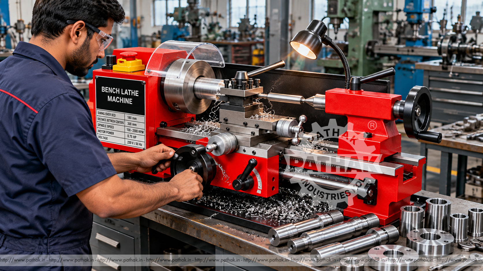
A compact lathe gives tool rooms, repair workshops, training centres, and small component makers a controlled way to machine rotational parts without the floor-space requirement of a full-sized engine lathe. A Bench Lathe Machine rotates a securely held workpiece while a guided single-point tool produces faces, diameters, shoulders, tapers, bores, grooves, and threads.
The Pathak Industries bench lathe is listed with a 180 mm swing over the bed, options of 200, 300, or 350 mm between centres, a 20 mm spindle bore, spindle speeds up to 2500 rpm, metric and imperial threading ranges, and a compact 700 × 300 × 300 mm overall size. This guide explains its working principle, common operations, setup, tooling, safety, maintenance, and selection considerations.
A bench lathe is a compact turning machine designed to sit on a rigid workbench or dedicated stand. Like a larger conventional lathe, it includes a headstock and spindle, bed, carriage, cross slide, compound slide, tool post, lead or feed arrangement, and tailstock. Its smaller work envelope suits short shafts, pins, bushes, sleeves, spacers, model components, repair parts, and prototypes.
Compact size does not make the machine a hand tool. The rotating chuck and workpiece, leadscrew, belts or gears, and cutting zone require the same disciplined setup and safety practices expected on larger machinery.
The workpiece is held in a chuck, collet, faceplate, or between centres. The spindle rotates it at a selected speed. A cutting tool is clamped in the tool post and moved along or across the work by the carriage, cross slide, and compound.
Longitudinal movement produces cylindrical surfaces and shoulders, while cross-slide travel faces the end or changes diameter. The compound can support short tapers, controlled infeed, and threading techniques. The tailstock supports slender work or holds tools for drilling, reaming, and related axial operations.
Material removal should occur in controlled passes. Speed, feed, tool geometry, depth, workholding, and support must all suit the material and component.
The stored bench-lathe specification lists:
Usable capacity depends on the chuck, jaws, tool post, tailstock position, work shape, fixture, and required tool clearance. A nominal swing does not mean every 180 mm-diameter part can be machined in every position.
Swing over the bed is the maximum theoretical diameter that can rotate above the bed. The listed 180 mm swing indicates the broad diameter envelope, but chuck jaws, carriage, cross slide, tool, and irregular part features can reduce practical capacity.
Distance between centres describes the available nominal length when work is supported by the headstock and tailstock centres. The 200, 300, and 350 mm options allow users to select a configuration around typical part lengths. Chuck-mounted work consumes some of this space, as do drill chucks and long tailstock tools.
Selection should be based on the complete setup rather than finished dimensions alone. Include chuck projection, centre drilling, tool access, support, and allowance for facing.
The 20 mm spindle bore can allow suitable round stock to pass through the spindle, making it practical to machine shorter sections from longer bar. Stock must fit safely and should not project unsupported from the rear where it can whip or strike surrounding objects.
The MT3 spindle taper and MT2 tailstock taper support compatible centres and tooling. Tapers must be clean and free from burrs before insertion. Dirt or damage can cause poor alignment, tool runout, unreliable holding, and difficulty removing accessories.
Facing produces a flat end square to the rotational axis. The tool moves across the end using the cross slide. A faced end often provides the reference for later length measurements or centre drilling.
The tool travels parallel to the spindle axis to reduce diameter and create a cylindrical surface. Measure after the tool clears and the spindle has stopped when the procedure requires hands near the work.
Different diameters are combined with controlled axial positions to produce stepped shafts, spacers, and locating shoulders. Tool nose geometry and approach direction influence corner form.
A drill held in the tailstock can start or enlarge an axial hole. Boring then uses a single-point tool to improve diameter, alignment, or finish. Tool rigidity and chip removal become increasingly important in deep holes.
Narrow tools create grooves or separate a completed part from bar stock. These operations demand correct centre height, minimal tool overhang, suitable speed, and rigid workholding.
The listed metric and imperial ranges allow selected screw pitches when the appropriate gears, setup, and procedure are used. Threading requires correct tool form, gear arrangement, spindle speed, infeed, and engagement timing.
The machine lists low and high ranges extending from about 100 to 2500 rpm. The correct speed depends on work diameter, material, cutting-tool material, operation, workholding, balance, and desired finish. Large diameters and interrupted cuts generally require more conservative speeds than small, well-supported parts.
Begin new setups cautiously. Excessive speed can increase heat, vibration, tool wear, and danger from an unbalanced component. Very low speed may produce poor cutting behaviour with some tools and materials. Follow approved cutting data and remain within the machine and chuck ratings.
High-speed-steel tools are versatile and can be ground for many workshop operations. Carbide inserts offer convenient edge replacement and can support higher cutting speeds where machine rigidity and power permit. Tool geometry must suit the work material and operation.
The cutting edge should normally be set at the work centreline. A tool that is too high or low can alter rake and clearance, leave a facing pip, affect diameter, and create problems during parting or threading. Use a centre reference or approved setting method.
Keep tool overhang short and clamp it securely. The compact 250 W machine benefits from sharp tools and sensible cut depths rather than forceful heavy cuts.
A three-jaw self-centring chuck is convenient for round and hexagonal stock. A four-jaw independent chuck supports square, irregular, or deliberately offset work and allows accurate centring with an indicator. Collets can provide precise, repeatable holding for compatible bar sizes.
Long slender work may need tailstock-centre support or a suitable steady. Work projecting through the spindle requires rear guarding and support. Never assume that tightening a chuck alone makes every setup safe; consider grip length, jaw engagement, cutting direction, balance, and centrifugal force.
Remove the chuck key immediately after use. Starting the spindle with a key left in the chuck can eject it at high speed.
The MT2 tailstock can support a centre, drill chuck, reamer, countersink, or other compatible tooling. Align and lock the tailstock before cutting. When using a centre, apply the appropriate lubrication and pressure; too little support permits vibration, while excessive force can heat or distort the work.
For drilling, begin with a faced surface and centre drill where needed. Clear chips regularly, especially in deep holes. Do not hold drills or workpieces by hand.
The metric version lists pitches from 0.4 to 2.0 mm, and the imperial version lists 12 to 52 threads per inch. Verify that the required pitch is included in the supplied gear and leadscrew arrangement. Do not infer that every pitch within the endpoints is available.
A threading tool must match the thread form and be aligned square to the work. The operator also needs a clear relief area or safe stopping method. Practice on suitable material before attempting a critical component, and check pitch with an appropriate gauge.
A bench lathe can support:
Actual suitability depends on material, dimensions, tolerance, finish, tooling, and required output. The machine should not be selected solely from part diameter.
The supporting bench must be rigid, level, and rated for the machine, work, tooling, and cutting forces. A flexible or uneven surface can affect alignment and encourage vibration. Secure the lathe using the manufacturer's mounting points while avoiding distortion of the bed.
Provide clear access to controls, gears or belts, lubrication points, chip collection, and the tailstock end. Lighting should illuminate the cutting zone without creating glare. Electrical supply, earthing, isolation, and protection must match the motor and local requirements.
Use micrometers, callipers, indicators, gauges, and thread tools appropriate to the tolerance. Measure clean surfaces without chips trapped between the instrument and work. Where thermal growth matters, allow the part to stabilise.
Taper on a nominally straight diameter can indicate tailstock influence, work deflection, tool wear, carriage alignment, or machine setup. Chatter can arise from excessive overhang, loose slides, poor support, unsuitable speed, dull tooling, or an overly ambitious cut.
Rotating chucks, jaws, workpieces, bar stock, leadscrews, and swarf can cause severe injury. Keep hands, loose clothing, jewellery, long hair, gloves, rags, and measuring tools away from rotation. Gloves should not be worn near rotating machinery where entanglement is possible.
Use guards as supplied, remove the chuck key immediately, and stop the spindle before measuring, clearing chips, or making adjustments that bring hands near the work. Use a brush or chip hook for swarf; never pull continuous chips by hand.
Isolate energy before changing chucks, servicing gears or belts, or performing maintenance. Eye protection and other PPE should follow the risk assessment, but they do not replace guarding and safe working distance.
Before each session, check lubrication, chuck condition, guards, tool clamping, slide movement, tailstock lock, cables, controls, and mounting. Clean chips without blowing them into bearings or guideways. Lightly protect bare metal surfaces from corrosion.
Monitor gib adjustment, backlash, spindle sound, belt condition, gear engagement, tailstock alignment, and electrical condition. Loose slides reduce accuracy; overtight slides increase wear and make controlled movement difficult.
Periodic maintenance should follow the machine documentation for spindle bearings, drive system, gears, leadscrew, lubrication, fasteners, and alignment. Keep a record of service and accuracy checks.
List the maximum stock diameter and length, finished part size, spindle-through requirement, materials, operations, thread pitches, tolerances, finish, and expected batch size. Include the complete chuck, tailstock, and tooling setup when checking capacity.
Compare centre-distance options, speed range, spindle bore, tapers, slide travel, motor power, threading equipment, included accessories, bench requirements, guarding, training, spares, and service support. Select useful working capacity rather than the smallest theoretical fit.
Pathak Industries can review part drawings and process requirements against the bench-lathe specification. Representative samples help confirm workholding and tooling needs.
The published swing is 180 mm. Practical diameter depends on the chuck, carriage, tool, work shape, and required clearance.
The product specification lists 200, 300, and 350 mm options between centres.
The listed through-spindle hole is 20 mm, allowing compatible bar stock to pass through when safely supported and guarded.
The machine lists a low range of approximately 100–1100 rpm and a high range of approximately 100–2500 rpm, subject to the published tolerance.
Yes. The listed versions cover ten metric pitches from 0.4 to 2.0 mm and eighteen imperial pitches from 12 to 52 TPI. Confirm the supplied gear set.
The spindle taper is listed as MT3 and the tailstock taper as MT2.
Yes. A compatible drill chuck or taper-shank tool can be used in the tailstock, provided the operation stays within the machine and tool capacity.
Provide part drawings, stock and finished dimensions, materials, operations, thread pitches, tolerances, batch sizes, workholding preferences, electrical supply, and required accessories.
The Pathak Industries Bench Lathe Machine provides compact conventional turning for small shafts, bushes, sleeves, adapters, threaded parts, prototypes, and repair work. Its 180 mm swing, 200–350 mm centre-distance options, 20 mm spindle bore, speed range up to 2500 rpm, and metric or imperial threading capability support varied light workshop operations.
Good results depend on rigid installation, secure workholding, sharp tools at correct centre height, suitable speed and cut depth, disciplined measurement, safe chip handling, and routine slide and spindle maintenance. Selection should be based on the complete part setup and required operations rather than nominal swing alone.