Head Office
117, Grand Trunk Road, Salkia Howrah-700013, Kolkata, India
 Hitesh PathakTue, May 20, 2025
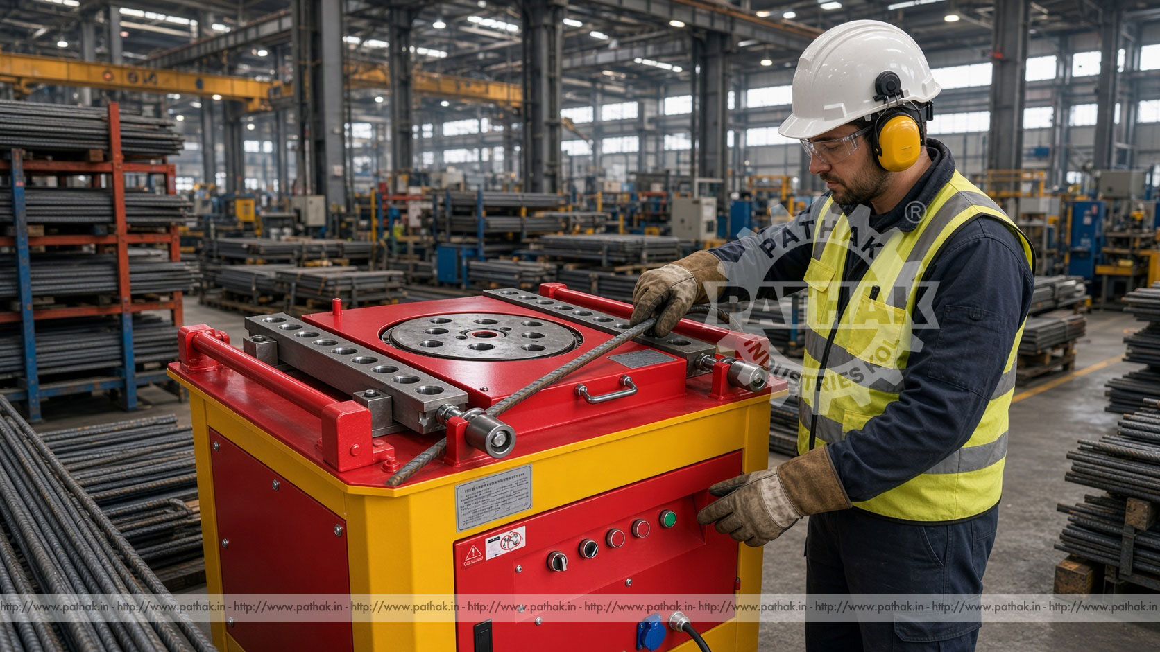
Reinforcement steel must be formed to match structural drawings before it can be placed in beams, columns, slabs, foundations, cages, and precast components. Manual bending can become slow and inconsistent when a project requires repeated angles and dimensions. A Bar Bending Machine provides a dedicated workstation where a powered disc and bending pins move located steel bar around a controlled centre, supporting more repeatable preparation for construction work.
The Pathak Industries product record lists three automatic models: TLP BB-32, TLP BB-36, and TLP BB-40. Their published bending ranges are 6–36 mm, 6–32 mm, and 6–40 mm respectively. Because several other rows in the imported source table are incomplete or displaced, this guide does not assign unsupported bending force, motor, noise, weight, or certification values. Final selection should always be based on confirmed technical documentation and the reinforcement grade actually being processed.
A bar bending machine forms reinforcing steel by holding the bar against fixed references while a powered bending pin moves it around a central mandrel or pivot. The machine table normally provides positions for pins, stops, or rollers that establish the bending geometry. As the disc turns through the set movement, the projecting length of bar is swept around the centre to form the required angle.
This method is suited to repeated construction shapes because the same setup can be used for multiple bars. It reduces dependence on improvised levers and uncontrolled floor-level bending. However, correct results still depend on bar grade, diameter, bend radius, pin arrangement, springback, and accurate marking or stops.
The operator identifies the bar from the bending schedule, confirms its diameter and grade, and selects a tooling arrangement that produces the required inside bend. The straight bar is placed against the locating points with the bend mark or dimensional reference in the correct position. Once the work area is clear, the cycle drives the bending disc through its configured movement.
The forming pin pushes the free portion of the bar around the centre pin while a stop or support resists unwanted movement. At the selected endpoint, the disc stops and returns so the bent bar can be removed. Automatic operation makes the mechanical sequence repeatable, but the operator must still verify the setup and check the first completed part.
TLP BB-32 is listed with a bending range of 6–36 mm. TLP BB-36 is shown with a 6–32 mm range, while TLP BB-40 is published at 6–40 mm. The model numbers and capacities do not follow a simple ascending pattern in the stored table, so buyers should not infer capability from the model suffix alone. Each proposed bar should be checked against the confirmed data for the selected machine.
Diameter is only one part of capacity. Reinforcement steel can vary in strength and ductility, while the bend radius and number of bars formed together change the load. The published range should therefore be read alongside permitted material grade, tooling, single- or multiple-bar operation, and the manufacturer’s bending chart. If any value conflicts with a project specification, obtain written confirmation before production.
A bend is not simply a sharp change in direction. The steel is stretched on the outside and compressed on the inside as it travels around the mandrel. A centre pin that is too small can create an excessively tight radius, damage the bar, or fail to meet the structural detailing requirement. The correct mandrel diameter is determined by the bar and the applicable project specification.
Larger pins produce a larger internal radius. Stops and rollers must be arranged so the bar remains supported without being trapped or marked unnecessarily. Tooling should be inspected before use; worn pins can change dimensions and allow unwanted play during the cycle.
A bending schedule identifies each reinforcement mark, bar size, shape, dimensions, quantity, and sometimes its location in the structure. Operators should work from the approved revision and keep different bar marks separated. Confusing two similar shapes can cause delays later when reinforcement is assembled or placed.
Dimensions may relate to outside, inside, or centreline geometry depending on the drawing convention. This must be understood before stops are set. A sample bar should be formed and measured against the schedule, with allowances made for bend geometry and springback. Once approved, it becomes a useful reference for the remaining batch.
Bars should be cut to the calculated length and identified before they reach the bender. Heavy contamination, attachments, or deformation can interfere with safe positioning. Inspect each piece for obvious defects and confirm that its diameter and grade match the job instruction.
Long bars need organised support on both sides of the machine. They should not block walkways or swing into nearby workers when the disc turns. Roller stands or a prepared support table can reduce dragging and help the operator maintain the dimensional reference without lifting the full weight unsupported.
The centre pin establishes the basic bend radius, while the bending pin provides the moving force. Locating stops establish where the bend begins. Their positions must suit the bar diameter and desired shape. Pins should be fully seated and retained using the method specified for the machine.
The control endpoint is set for the required angle, allowing for elastic recovery after the bar is released. This springback can vary with grade, diameter, and radius. Rather than repeatedly altering the machine without records, operators should form a trial piece, measure it, make a controlled correction, and document the approved setting.
Bar bending machines can help prepare straight bars with end bends, L-shaped bars, U-bars, links, stirrups, and multi-bend reinforcement where the geometry fits the machine and approved tooling. These parts may be assembled into column and beam cages, footing reinforcement, slab details, precast elements, and other concrete structures.
Not every complex shape should be formed in one uninterrupted operation. Multiple bends require a sequence that leaves room for the already formed legs to clear the table and machine body. The sequence should also preserve a reliable reference so dimensional errors do not accumulate from one bend to the next.
Typical users include rebar yards, civil contractors, precast plants, infrastructure projects, and construction-material preparation facilities. A central bending station can supply organised batches to cage assembly or site placement. It can also make fabrication easier to monitor because approved settings and inspection can be concentrated at one workstation.
On a changing construction project, mobility and protection from weather may be important. In a permanent rebar shop, material flow, storage racks, cutting stations, tagging, and batch control may have greater influence on productivity. The machine should be placed where straight stock can enter and formed pieces can leave without crossing unsafe routes.
Repeatability begins with a stable machine, unworn tooling, and consistent input bars. Positive stops reduce reliance on visual marks, while an approved sample allows quick comparison. Measuring the first piece and taking periodic samples during a long batch can reveal movement of stops or changes in material behaviour.
A setup sheet should record bar mark, grade, diameter, cut length, tooling, stop positions, angle setting, bending sequence, and inspection dimensions. This is especially useful when the same component returns in later production. Traceable settings reduce trial work while still requiring a first-off confirmation.
Check how the drawing dimension is defined, verify the cut length, and confirm the stop reference. Measuring from an inconsistent end can shift every bend in the batch.
Review the endpoint setting and springback correction. Confirm that the bar is seated against the same references during every cycle.
Use the required centre pin or mandrel for the reinforcement specification. Do not substitute a smaller pin merely to obtain a compact shape.
Keep each bend in the intended plane and support the formed legs. Marking orientation and following a planned sequence helps prevent the bar from being flipped incorrectly.
The rotating disc, bending pins, and moving bar create crushing, trapping, and striking hazards. No one should stand inside the sweep of the workpiece. Hands must remain clear of pins and stops whenever motion is possible. Guards and emergency controls should be checked and used as provided.
Long reinforcement can move suddenly as it bends, so the surrounding area needs a clearly controlled zone. Operators require training and suitable protective equipment for handling steel. Adjusting pins, clearing a jam, cleaning, or servicing requires the machine to be isolated according to its instructions. Bars should never be held in a way that places the body between the work and a fixed object.
Before use, inspect the table, disc, pins, stops, guards, controls, fasteners, and electrical cable. Remove scale and debris that can prevent tooling from seating correctly. Bent, cracked, or badly worn pins should be removed from service rather than used with an improvised correction.
Lubrication, gearbox, motor, bearings, electrical components, and drive mechanism should be maintained at the intervals specified for the machine. Listen for abnormal noise and investigate looseness or delayed stopping before production continues. Service records help identify wear trends and support consistent bend quality.
List the bar grades and diameters used on typical projects, then identify the largest required bend and minimum permitted radius. Record daily quantities, shape complexity, longest stock, available electrical supply, and whether the machine will work on site or in a fixed yard. These facts provide a better basis for selection than choosing the largest model name.
Compare confirmed capacity for the actual steel grade, tooling supplied, angle control, operating method, protection, machine footprint, material-support needs, and service access. If multiple bars may be bent together, that application must be specifically approved. Pathak Industries can review a representative bending schedule before the final model and accessories are agreed.
It forms reinforcing steel into approved shapes for concrete beams, columns, slabs, foundations, cages, precast elements, and related civil work.
The product record lists automatic TLP BB-32, TLP BB-36, and TLP BB-40 machines.
The stored table shows 6–36 mm for BB-32, 6–32 mm for BB-36, and 6–40 mm for BB-40. Confirm these ranges against the required steel grade before ordering.
Only if that combination is explicitly permitted by the machine’s confirmed capacity and tooling guidance. Combined load depends on bar number, diameter, grade, and bend geometry.
The powered disc travels to an established endpoint. A trial bend is measured and the setting is corrected for springback before repeat production begins.
It establishes the inside bend radius. Using an unsuitable pin can damage the reinforcement or produce a shape that does not comply with the approved detailing.
Common causes include loose stops, worn pins, incorrect references, mixed bar grades, variable cut lengths, poor support, and undocumented setting changes.
Provide bar grades, diameter range, bend radii, typical schedules, daily quantities, longest stock, electrical supply, installation location, and desired tooling.
A bar bending machine makes repetitive reinforcement preparation more organised, but its results depend on the process around it. Accurate cutting, verified schedules, correct pins, controlled springback, safe material handling, and dimensional inspection should be treated as one workflow. A machine selected for the real bar grade and shape range will be more useful than one chosen by diameter alone.
Review the supported models on the Bar Bending Machine product page and share representative bending schedules with Pathak Industries. The final bar capacity, tooling, electrical arrangement, controls, dimensions, and installation requirements should be confirmed in the technical offer.