Head Office
117, Grand Trunk Road, Salkia Howrah-700013, Kolkata, India
 Hitesh PathakWed, Sep 3, 2025
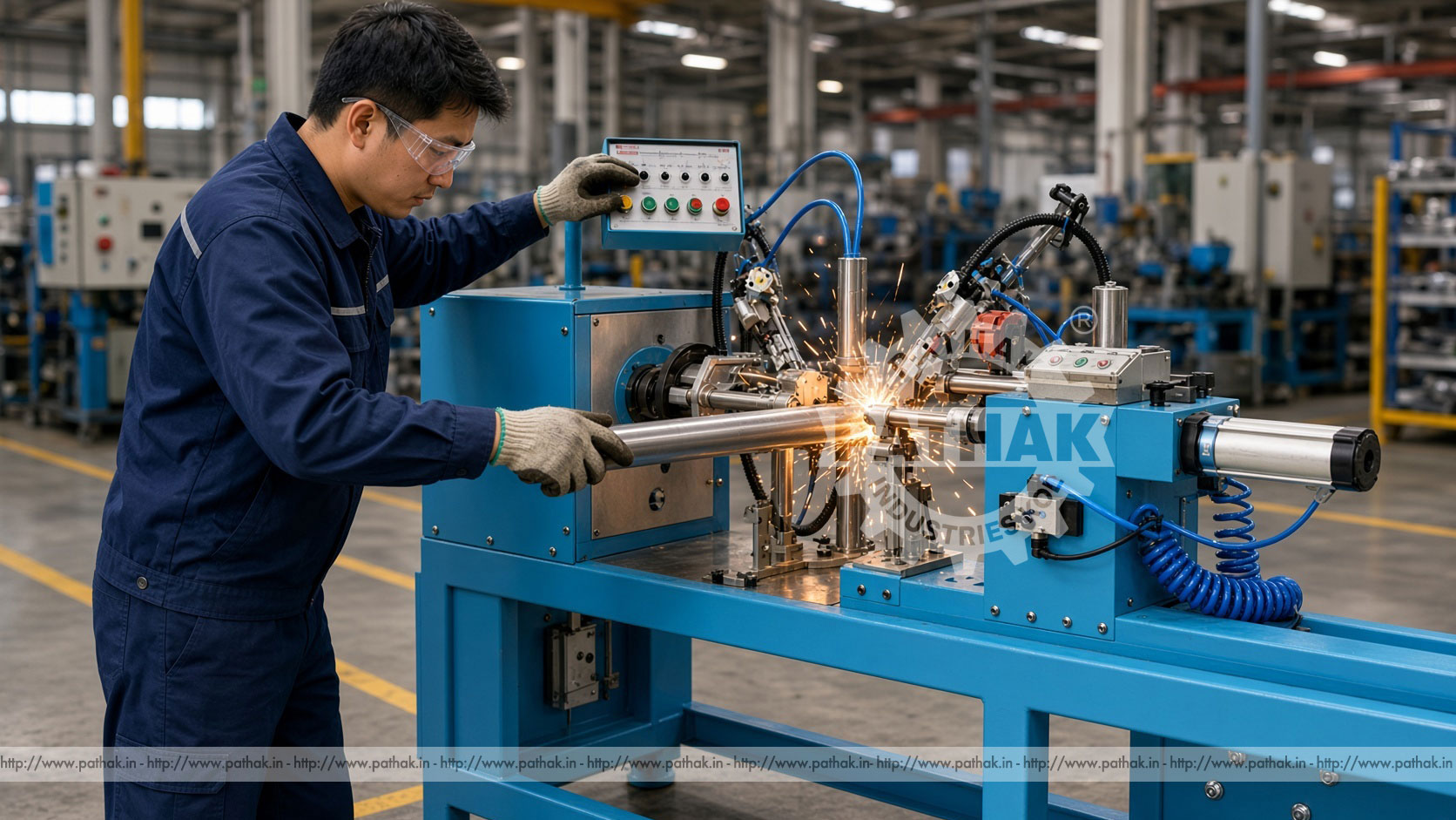
Conveyor idlers appear simple from the outside, yet their production depends on controlled alignment at several connected parts. A tube, bearing housings, and end assemblies must share a consistent axis so that the completed roller can rotate as intended. Welding these components without disturbing their location is therefore a specialised manufacturing task. The Idler Welding Machine Twin Head Automatic Pneumatically Operated is designed around this operation, holding the roller concentrically while circumferential end joints are produced.
Its twin-head arrangement supports opposed or paired processing in one setup, while pneumatic operation provides controlled clamping and movement within the configured cycle. Automatic functions reduce repeated manual intervention, but they do not remove the need for correct component preparation, fixture adjustment, welding parameter development, inspection, and trained supervision. Because the current product record does not publish numerical working ranges, this guide explains the machine and its selection criteria without inventing tube diameters, lengths, production rates, electrical loads, or air-pressure figures.
An idler welding machine is a dedicated production station for joining end components to conveyor idler tubes. Instead of asking an operator to position a cylindrical shell and weld each end as an unrelated manual job, the machine brings workholding, alignment, rotation or welding motion, and cycle control into a repeatable arrangement. Fixtures locate the idler shell and bearing-housing assemblies so the circumferential joints can be made around a controlled centreline.
“Twin head” describes the paired working arrangement at the two ends of the roller. Depending on the final configuration, the heads support welding at opposed ends or coordinated processing in the same setup. This reduces the need to remove, reverse, and relocate the roller between its end joints. The practical result can be more consistent handling and a better organised production sequence.
A conveyor roller rotates around its bearing axis. If the shell, bearing housings, and end components are not located concentrically before welding, the finished assembly may develop runout, vibration, irregular rotation, or uneven loading. Heat from welding can also introduce distortion, which makes controlled fixturing and a balanced sequence important.
The welding station cannot correct inaccurately prepared components automatically. Tube ends, housing seats, and mating surfaces need to be clean and dimensionally suitable before loading. Fixtures must contact the intended references, and components should enter the station without burrs, heavy scale, oil, or deformation that prevents reliable seating. Upstream cutting, forming, and housing preparation therefore have a direct effect on welding results.
A typical cycle begins with loading the prepared idler shell and its end components into dedicated supports. The operator confirms that the parts are seated against their references. Pneumatic actuators then clamp or advance the working elements according to the machine’s design, holding the assembly in position for welding. Interlocks and controls manage the authorised sequence.
Once the part is secured, the machine coordinates the welding operation around the circumferential joints. This may involve controlled rotation of the workpiece, movement of welding heads, or another configured relationship between torch and component. The exact welding process, torch arrangement, filler delivery, shielding system, and parameters must be confirmed for the supplied machine rather than inferred from the product name.
After the programmed joint cycle, the heads return or the clamps release so the completed assembly can be removed. The operator then checks the weld, part condition, and required dimensions before the next piece is loaded. Automatic operation makes the sequence repeatable; inspection remains necessary to detect changes in consumables, component fit, gas delivery, alignment, or heat input.
Pneumatics are useful for repeated clamping and positioning because actuators can apply a controlled mechanical action through a straightforward air circuit. In an idler welding station, pneumatic elements may support part holding, head positioning, or other configured cycle movements. Their performance depends on clean, dry air supplied at the pressure and flow specified for the machine.
Air preparation matters. Moisture, contamination, unstable pressure, leaking lines, and damaged seals can cause slow or inconsistent movement. The installation should include the filtration, regulation, isolation, and drainage provisions required by the manufacturer. Operators should never increase pressure in an attempt to compensate for a mechanical obstruction, incorrect adjustment, or worn component.
Handling a roller once for paired end work can simplify the production route. The same central setup can maintain the relationship between the shell and both end assemblies, reducing errors associated with turning and re-referencing the part. Coordinated heads can also support a balanced workflow where preparation, welding, unloading, and inspection follow a predictable sequence.
The arrangement is particularly relevant to repeat production because fixtures can be established for a defined idler family. Changeover remains an important consideration when a factory produces several shell lengths, diameters, or housing styles. A useful machine configuration should offer the required adjustment while retaining positive, repeatable location after the setup is changed.
Reliable joints begin with controlled incoming parts. Tube ends should be cut square to the required standard and should not contain burrs that prevent the housing from seating. Bearing housings and other end elements need consistent mating dimensions. Weld areas must be free from oil, excessive rust, paint, moisture, and debris that could contaminate the joint.
Operators should confirm component identity before assembly. Similar-looking housings or shells may belong to different product variants. Gauges, labelled bins, and route cards can prevent mixing. Where a tack or preliminary assembly operation is specified, it should locate the parts without creating an obstruction for the automatic welding heads.
A circumferential joint requires consistent travel around a round component. Changes in stand-off, torch angle, rotation, electrical contact, shielding, or part fit can affect penetration and bead profile. Fixtures and motion systems create the basis for repeatability, while approved welding parameters define the process window for the particular material and joint.
Heat should be considered at both ends of the roller. An unsuitable sequence or excessive input may distort the shell or alter component location. The production method should be proven through trials and appropriate inspection before volume work begins. Settings should then be documented by idler type so operators do not rebuild the process from memory at each changeover.
This machine is intended for conveyor roller factories and idler production cells that join bearing housings or related end components to cylindrical shells. Such idlers may become part of belt conveyor systems used for material movement in industrial facilities. The welding station occupies one stage within a larger route that may include tube cutting, housing preparation, assembly, machining, bearing installation, sealing, finishing, balancing, and inspection.
Its strongest use case is repeat manufacture of compatible assemblies. A repair shop processing occasional unrelated rollers may have different priorities from a production unit making defined idler families. Buyers should evaluate expected batch size, variant frequency, upstream component consistency, and downstream inspection before deciding how much automation is appropriate.
Fixtures should reference functional surfaces without damaging the shell or housing. They need enough rigidity to resist welding movement while allowing convenient loading and removal. Replaceable or adjustable locating elements may be useful where several idler sizes are required, provided each setup can be verified and secured.
A documented changeover procedure should identify the fixture components, head positions, stops, pneumatic adjustments, welding settings, and inspection sample needed for the new job. The first piece after a change should receive a complete check. Retaining approved setup sheets reduces downtime and makes the cause of any later variation easier to trace.
Inspection should address both the weld and the function of the assembly. Visual checks can identify irregular bead shape, missed areas, excessive spatter, cracks, undercut, surface contamination, and other visible concerns. Dimensional checks can confirm housing location, overall length, and alignment according to the product drawing.
Rotation and runout checks may be relevant because an acceptable-looking weld does not guarantee that the roller axis has remained correct. The exact inspection method and acceptance criteria should follow the intended idler design and quality plan. Where the application demands additional examination, the appropriate qualified procedure should be used rather than relying only on appearance.
Start with a component matrix covering minimum and maximum shell length, diameter, wall form, bearing-housing geometry, material, joint design, and required weld process. Add the expected production volume, typical batch size, changeover frequency, and quality checks. These facts define the working envelope more accurately than the general label “idler welding machine.”
Then confirm fixture adjustment, head travel, permitted workpiece weight, supported welding equipment, rotation or travel control, pneumatic supply, electrical supply, guarding, fume extraction needs, and integration with existing material handling. Buyers should also consider whether one operator can safely load the longest or heaviest intended roller or whether assisted handling is required.
Because no numerical capacity table is currently published for this product, every required size and utility should be confirmed in the final technical offer. Pathak Industries can review representative drawings and production details to establish whether the proposed configuration matches the intended idler range.
The station combines welding hazards with automatic movement and pneumatic stored energy. Operators need protection from arc radiation, heat, sparks, fumes, electric shock, moving heads, rotating work, and pinch points. Guards, screens, interlocks, emergency stops, and extraction provisions must be used as supplied and checked before production.
Loading should occur only in the authorised machine state. Hands and tools must be clear before clamping begins. Adjustment, cleaning, clearing a jam, or changing fixtures requires isolation of electrical, pneumatic, and other stored energy according to the machine instructions. Welding personal protective equipment remains necessary wherever exposure can occur, even when much of the cycle is automatic.
Daily checks should cover fixtures, clamps, guards, interlocks, cables, hoses, connectors, torch condition, consumable delivery, and visible leaks. Spatter should be removed using the approved method before it prevents accurate seating or movement. Locating faces must be protected because wear or buildup at these points can shift every subsequent assembly.
Pneumatic filters and drains require attention, while cylinders, valves, guides, bearings, drives, and electrical systems should follow the scheduled maintenance plan. Welding cables and return connections need secure contact without damaged insulation. Maintenance records, along with setup and inspection data, help the production team identify whether variation originates in the machine, fixture, consumables, or incoming parts.
It holds a conveyor idler assembly concentrically and supports welding of circumferential joints at its opposed ends within one organised setup.
Pneumatic actuators provide repeatable clamping or positioning actions in the configured cycle. They require a clean, stable air supply and correctly maintained controls.
No. The operator still verifies parts, loads the assembly, selects the approved setup, monitors the cycle, unloads safely, and completes the required inspection.
The current product record does not publish numerical diameter or length limits. Buyers should submit component drawings and confirm the complete working range in the technical offer.
Dedicated fixtures locate the shell and end components around a controlled axis. Results also depend on component accuracy, correct adjustment, fixture condition, heat control, and inspection.
Confirm electrical power, compressed-air quality and demand, welding consumables, shielding requirements where applicable, fume extraction, earthing, and safe material handling for the supplied configuration.
Cycle time is only one factor. Loading, component preparation, weld sequence, part size, changeovers, inspection, consumable replacement, and operator workflow all influence actual output.
Keep fixtures and locating faces clean, inspect pneumatic and welding systems, maintain guides and drives, verify safeguards, and replace worn consumables according to the prescribed schedule.
A twin-head automatic pneumatic idler welding machine is most effective when it is treated as part of a complete production method. Accurate incoming components, repeatable fixtures, proven welding parameters, controlled utilities, trained loading, and functional inspection all contribute to the finished roller. Automation organises those elements; it cannot replace them.
Review the Idler Welding Machine Twin Head Automatic Pneumatically Operated product page and provide representative idler drawings, materials, variants, and production expectations when requesting a configuration. All working ranges, welding equipment, utilities, accessories, and safety provisions should be confirmed before ordering.