Head Office
117, Grand Trunk Road, Salkia Howrah-700013, Kolkata, India
 Hitesh PathakMon, Jul 14, 2025
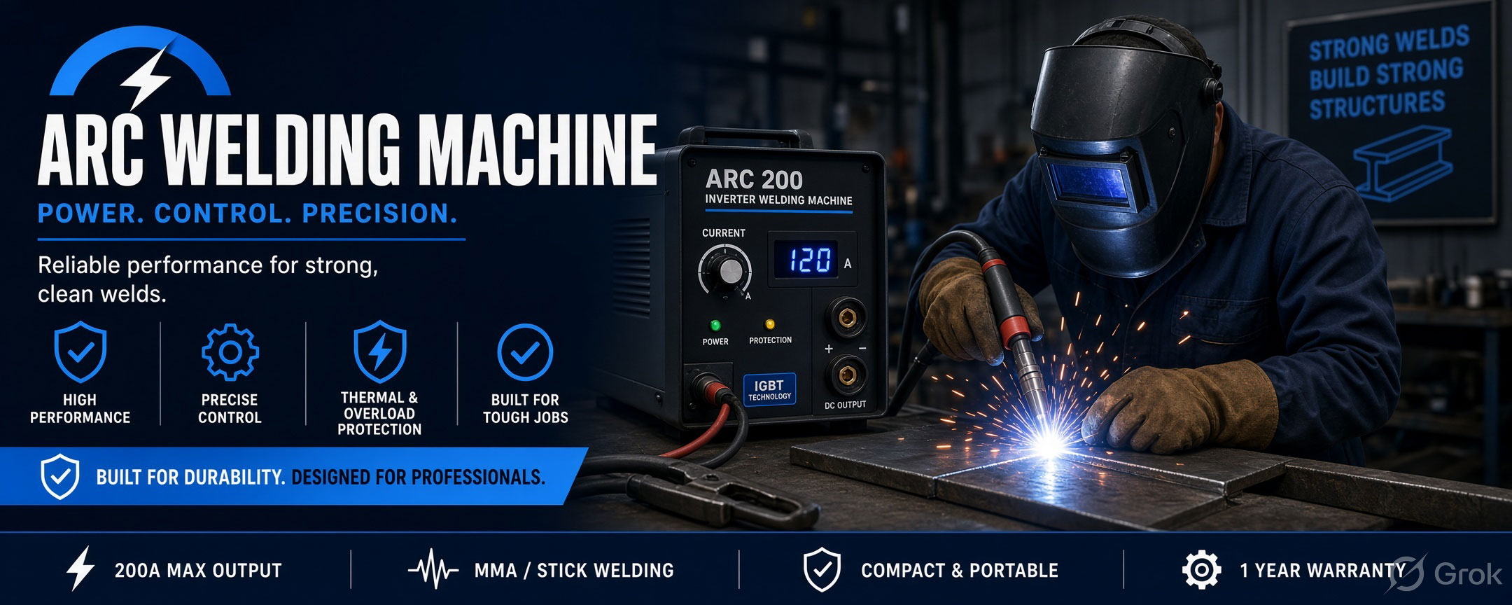
Arc welding remains one of the most practical ways to join steel parts in fabrication, repair, construction, and general workshop work. A compact power source, suitable electrode, correctly prepared joint, and trained operator can produce durable connections across a wide variety of jobs. The ARC Welding Machine 200 AMPS is positioned for users who need a dedicated machine for controlled metal joining without making the welding station unnecessarily complicated.
The “200 AMPS” designation identifies the machine’s stated current class. It should not be treated as a guarantee that every electrode, material thickness, or duty cycle can be handled at the maximum setting. Actual suitability depends on the selected electrode, joint design, material, welding position, incoming electrical supply, operating duration, and the specifications confirmed for the supplied model. This guide explains those practical considerations without assigning unsupported performance figures to the machine.
An arc welding machine provides controlled electrical power for creating an arc between an electrode and a metal workpiece. The heat generated by that arc melts material at the joint. As the operator travels along the prepared seam, the molten metal forms a weld pool and then solidifies into a joined section. In a common manual metal arc or stick-welding process, the consumable electrode contributes filler metal while its flux coating helps protect the weld area.
A 200-amp-class machine offers an adjustable current range intended to accommodate different welding tasks within its rated capability. The operator does not simply set the machine to its highest output. Current is selected to suit the electrode type and diameter, joint form, base material, welding position, and desired penetration. Correct adjustment is central to arc stability, bead shape, fusion, spatter control, and electrode life.
The welding circuit includes the power source, electrode lead and holder, work return lead and clamp, electrode, and workpiece. Once the work clamp has sound electrical contact and the electrode touches and separates from the work, an arc can be established. The operator maintains an appropriate arc length and moves the electrode along the joint at a controlled angle and travel speed.
Several actions occur together. Electrical energy generates intense local heat, the electrode core melts, and the edge of the base material enters the weld pool. The flux coating produces shielding gases and slag that help protect the hot metal from the surrounding atmosphere. After cooling, the slag is removed so the bead can be inspected. Where a multi-pass joint is required, cleaning between passes is important because trapped slag can weaken the finished weld.
Welding current influences how easily the electrode starts, how deeply heat acts at the joint, and how the molten pool behaves. A setting that is too low may produce an unstable arc, poor fusion, or an electrode that repeatedly sticks. Excessive current can increase spatter, undercut the joint edges, overheat the electrode, or make the weld pool difficult to control.
The correct setting should follow the electrode maker’s guidance and the approved welding procedure for the job. Operators often begin within the recommended range and make a controlled adjustment after examining arc behaviour and a test bead. Welding position matters as well: a setting that works on a flat test piece may require reassessment when the joint is vertical or overhead.
An ARC Welding Machine 200 AMPS may support a broad range of general joining and repair activities when the job falls within the machine’s confirmed rating. Common environments include fabrication shops, maintenance departments, construction support workshops, agricultural equipment repair facilities, automobile body and chassis workshops, and small production units.
Typical work can include joining brackets, frames, gates, supports, fixtures, structural subassemblies, workshop furniture, and prepared repair sections. It may also be used for maintenance tasks where a worn or damaged steel component must be restored through a controlled welding procedure. The machine should always be matched to the specific material and joint rather than selected only because the workpiece appears visually small or large.
Good welding begins before the arc is struck. Oil, moisture, paint, rust, scale, and other contaminants can interfere with arc stability and introduce defects. The joint area and the point used by the work clamp should therefore be cleaned appropriately. Parts must then be aligned, supported, and restrained so they do not move unexpectedly as heat is applied.
Joint geometry affects penetration and accessibility. Depending on the material and required connection, preparation may involve square edges, a bevel, a root opening, tack welds, or multiple passes. These details should follow the drawing or an approved procedure. Tack welds must be sound because defective tacks can become part of the final joint or cause alignment problems during welding.
Electrodes are not interchangeable simply because they fit the same holder. Their classification relates to factors such as deposited metal properties, suitable welding positions, flux characteristics, polarity requirements, and operating behaviour. Selection should match the base material and service requirement of the joint. Where the product documentation or job procedure specifies polarity, the welding leads must be connected accordingly.
Storage is also important. Flux coatings can be damaged by impact or affected by unsuitable moisture exposure. Electrodes should remain clean, dry, and correctly stored in accordance with their manufacturer’s instructions. A contaminated or cracked coating can contribute to an erratic arc and weld discontinuities even when the machine itself is functioning correctly.
Repeatable welds result from a combination of machine condition, preparation, technique, and inspection. The operator needs to control arc length, electrode angle, travel direction, and travel speed while observing the weld pool. Moving too quickly may leave a narrow bead with inadequate fusion; moving too slowly can create excessive buildup and heat input. An arc held too long can increase spatter and reduce shielding effectiveness.
For repeated components, a simple fixture can improve part location and joint consistency. It also helps to establish a written setup covering material preparation, electrode selection, current setting, polarity, pass sequence, and cleaning requirements. Test pieces can be used when a new combination is introduced. Finished welds should be assessed using the inspection level appropriate to the component and its service.
Before installation, confirm that the workshop supply matches the machine nameplate and installation instructions. The circuit, protective devices, earthing arrangement, plugs, cables, and isolation method should be assessed by a qualified person. Long or undersized extension leads can cause voltage drop and should not be improvised as a substitute for a properly planned supply.
The welding location needs dry footing, adequate lighting, effective ventilation, and sufficient clearance around the equipment. Leads should be routed away from sharp edges, hot metal, vehicle paths, water, and places where workers may trip. Screens may be required to protect nearby people from arc radiation. Flammable material must be removed or controlled before work begins, and an appropriate fire watch may be necessary for hot work.
Arc welding exposes the operator and nearby workers to intense light, heat, sparks, hot metal, fumes, electrical hazards, and fire risk. A suitable welding helmet with the correct filter shade, protective clothing, welding gloves, and safety footwear are basic requirements. Clothing should cover exposed skin and resist ignition. Eye protection remains important during slag removal and grinding, even after the welding helmet is raised.
Ventilation should control fumes at their source without disrupting the shielding action around the weld. Extra precautions are needed in confined spaces, on containers, near coated materials, or where the previous contents of a workpiece are unknown. Never weld a closed container or a component that has held a hazardous substance unless it has been made safe under a competent procedure. Operators must follow the machine manual and the site’s electrical and hot-work controls.
A brief pre-use inspection can prevent many interruptions. Check the input cable, electrode lead, return lead, holder, work clamp, connectors, controls, vents, and enclosure for damage or overheating. Loose or contaminated connections create resistance, which can reduce performance and generate unwanted heat. Damaged insulation or exposed conductors require the machine to be isolated until properly repaired.
Cooling openings should be kept clear, and accumulated dust should be removed only by the method recommended in the manual. Internal electrical work belongs to qualified service personnel. Maintenance intervals depend on the working environment and frequency of use; a machine in a dusty fabrication shop may need attention more often than one used occasionally in a clean area. Service records help identify recurring cable, connector, or cooling problems.
Start with the jobs rather than the headline current. List the base materials, normal thickness range, electrode classifications and diameters, welding positions, joint types, and expected operating time. Then verify the machine’s output range, rated duty cycle at relevant currents, supply requirements, polarity options, lead connections, cooling method, ingress protection, and supported accessories.
Portability may matter for site repair, while robust leads and accessible service support may be more valuable in a fixed production bay. Buyers should also consider local installation conditions, operator training, consumable availability, and the space needed to work safely. Pathak Industries can use these application details to help identify whether this model matches the proposed welding work, but the final selection should be based on confirmed technical documentation.
Check that the current is suitable for the electrode, the work clamp has clean contact, and the operator is establishing the arc correctly. Also inspect the leads and connectors for excessive resistance.
Confirm electrode condition, polarity, current setting, supply stability, and cable connections. Surface contamination and excessive arc length can also cause irregular behaviour.
Review current, arc length, electrode angle, polarity, and surface cleanliness. Spatter can arise from several interacting setup and technique issues, so changing one parameter at a time makes diagnosis clearer.
Reassess joint preparation, heat input, travel speed, electrode access, and pass placement. A visually filled joint is not necessarily a properly fused joint; critical work requires the appropriate inspection procedure.
It identifies the stated current class of the product. Usable output, duty cycle, electrode compatibility, and supply requirements must still be confirmed from the technical data for the exact machine.
The product is presented as an arc welding machine. Confirm the supported process, polarity, and compatible electrode types in the supplied documentation before selecting consumables or planning a job.
It may be suitable for fabrication, repair, and maintenance tasks that fall within its confirmed rating. Material, joint design, electrode, duty cycle, supply, and required weld quality all affect suitability.
Use the electrode manufacturer’s recommended range and the approved procedure for the material, joint, and position. Begin with a test weld where appropriate and adjust only after observing the arc and bead.
The clamp completes the welding circuit. Poor contact caused by rust, paint, dirt, a loose connection, or damaged cable can contribute to difficult starting, unstable output, and unwanted heating.
Inspect leads, insulation, connections, holder, clamp, controls, enclosure, and cooling openings. Keep the unit clean and dry, follow its service schedule, and have internal repairs completed by qualified personnel.
Pricing can depend on the machine configuration, output characteristics, duty rating, supplied leads and accessories, protection features, installation needs, freight, and after-sales support. A quotation should be evaluated against the intended application.
The ARC Welding Machine 200 AMPS can form the centre of a straightforward welding station when it is correctly matched to the job. Its value comes from controlled current, sound installation, suitable electrodes, disciplined joint preparation, and trained operation—not from using the maximum setting for every task. Buyers who define their materials, electrodes, joint requirements, and production pattern before ordering are better placed to select a machine that supports reliable daily work.
For application guidance, review the ARC Welding Machine 200 AMPS product page and provide Pathak Industries with details of the intended material, joint type, electrode, electrical supply, and expected usage. Confirm the final specification and accessories before purchase.