Head Office
117, Grand Trunk Road, Salkia Howrah-700013, Kolkata, India
 Hitesh PathakTue, Dec 17, 2024
Turning a drawing into a cut metal profile requires more than a plasma arc. The sheet must be supported, the torch must follow the programmed path, cutting height must remain controlled, motion must stay coordinated through corners and curves, and the plasma source must suit the material and thickness. A CNC plasma table brings these functions together in a repeatable cutting station.
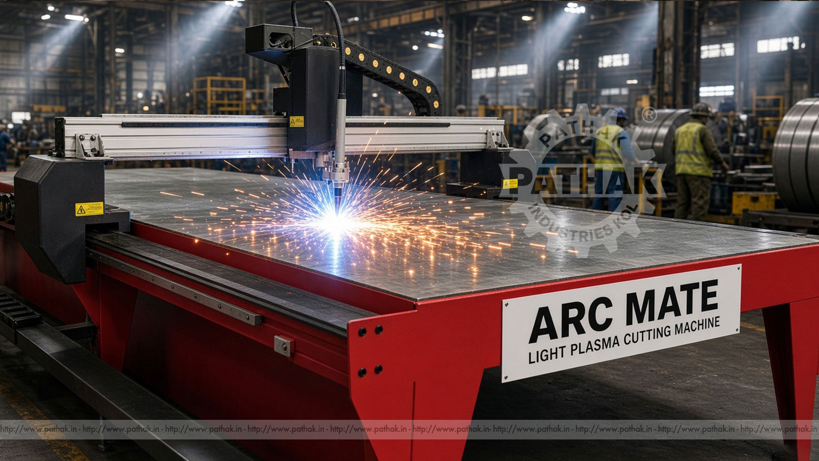
The Arc Mate Light Plasma Cutting Machine from Pathak Industries is listed as the Arcmate Lite PC1530PL tabletop model. Its published configuration includes dual-drive stepper motion, automatic Z-axis torch movement, a dedicated CNC controller, nesting software, and a water-table base. This article explains how that system works, what its documented figures mean, where it may be used, and which setup, safety, and maintenance factors affect practical results.
The Arc Mate Light is a computer-controlled plasma cutting table for producing profiles from suitable electrically conductive material. A CNC system moves the torch across the table in the X and Y directions according to a prepared cutting program. The torch generates a plasma arc that melts a narrow path through the material, while the gas flow expels molten metal from the cut.
The machine is described as a light tabletop configuration. “Light” refers to the product arrangement, not to permission to ignore material handling, guarding, fumes, electrical hazards, or fire risk. The table, selected plasma source, compressed-air system, CNC program, torch consumables, and workpiece must operate as a coordinated process.
Compared with manual plasma cutting, programmed motion can improve consistency when producing repeat profiles, holes, brackets, plates, panels, and fabrication blanks. Final quality still depends on material condition, plasma capacity, consumables, height, speed, gas quality, program geometry, and machine setup.
The process begins with a part profile and cutting layout. Nesting software is used to arrange one or more shapes within the available sheet area and prepare the cutting sequence. The program is transferred to the CNC controller, where the operator checks orientation, dimensions, starting position, and process settings.
The sheet is placed on the table and connected according to the plasma-system requirements. The machine positions the torch at the programmed start. During cutting, the controller coordinates X-Y movement while the plasma source creates the arc. The Z-axis system controls vertical torch movement so the torch can approach, pierce, cut, and clear the work as required by the approved setup.
Compressed air is the listed process gas. Its pressure, flow, cleanliness, and dryness influence arc stability and consumable condition. The plasma power source determines much of the available piercing and cutting capability, which is why the product table states that capacity depends on the selected plasma rating.
The machine uses a dual-drive 86-series stepper-motor configuration. Maximum travel speed is listed at 6000 mm/min, and published working accuracy is ±0.15 mm. These figures describe the motion platform; actual cut dimensions can also be affected by kerf, heat, plate movement, consumables, torch height, material, and the selected cutting parameters.
The cutting head is specified for plasma with automatic Z-axis up-down movement. Torch lifting distance is listed at less than 100 mm. A wireless remote is provided for X-Y axis alignment, helping the operator position or reference the moving system during setup.
The documented cutting-capacity range is 1–16 mm, depending on the plasma rating. This condition is important: the table itself does not determine the thickness that can be cut. Material type, plasma source, torch and consumables, available air, desired quality, and whether the operation is piercing or edge-starting all matter.
The controller has a 7-inch wide color screen and is described as a dedicated CNC automation controller for plasma and oxy-fuel. Fast Cam Basic is listed as the nesting software. The standard water table has a published load-carrying capacity of 600 kg.
Machine input is listed as single-phase 220 V, 50 Hz, plus the electrical requirement of the selected plasma source. Installation area is published as 2.4 m wide × 3.7 m long × 1.5 m high. Actual site planning should add operator, loading, ventilation, electrical, air-service, and maintenance clearances.
A plasma gantry spans the cutting table, so coordinated movement on both sides is important. The listed dual-drive arrangement moves the gantry along its axis while another motion axis positions the torch across the span. When the drive, guides, structure, and controller remain correctly aligned, the torch can follow programmed paths consistently.
Mechanical looseness, contamination on guide surfaces, unequal drive behavior, or an out-of-square gantry can affect corners, circles, and dimensional repeatability. Routine inspection should therefore include the complete motion system rather than only the torch.
Maximum rapid-travel speed should not be confused with correct cutting speed. Cutting speed must be selected according to the material, thickness, plasma source, amperage, consumables, and desired quality. Rapid travel is movement capability between cutting positions; it does not establish a universal cutting parameter.
Distance between the torch and plate affects plasma behavior. The torch may need one height for piercing and another for cutting, while uneven or thermally distorted sheet can change the physical surface beneath the moving torch. Automatic Z-axis movement gives the system a means to manage vertical approach and clearance according to its configured process.
Incorrect height can shorten consumable life, widen the kerf, increase bevel, cause misfires, or risk torch contact. The operator must therefore set and maintain the system according to the plasma-source and torch documentation. The published lifting distance of less than 100 mm describes available vertical movement but does not replace correct process settings.
Plate condition also matters. Heavy rust, scale, coatings, oil, or severe warping can affect electrical contact, cutting stability, fume generation, and height behavior. Material should be evaluated and prepared according to the workshop procedure.
A water table supports the cutting bed over a water-filled section. For an appropriate process, it can help capture some sparks, slag, and airborne material close to the cut. It also provides a defined base for supporting plate and cut parts. The Arc Mate Light table is listed with a 600 kg load-carrying capacity.
The load rating must include the workpiece and any other permitted load on the table. Sheets should be placed without impact or localized overload. Slats, supports, and the water system need cleaning because accumulated slag can affect support, drainage, and maintenance access.
A water table does not eliminate the need for fume assessment or ventilation. The material being cut, coatings, water condition, cut duration, and workplace layout all influence exposure. Facilities should establish suitable extraction, ventilation, water maintenance, and waste-handling practices.
The machine may suit sheet-metal and general fabrication workshops, maintenance departments, production units, training facilities, and businesses preparing profiles for welding or assembly. Typical work can include brackets, base plates, gussets, covers, flanges, frames, signs, repair patches, and other two-dimensional profiles within the machine and plasma-source capability.
CNC cutting is particularly useful when the same profile is needed repeatedly or when several different parts can be nested on one sheet. A planned nest can reduce unused material, but efficiency also depends on sensible part spacing, kerf compensation, lead-ins, cut order, and the ability to remove finished parts safely.
Small holes, narrow webs, closely spaced cuts, and heat-sensitive geometry may require special attention. A shape that appears simple in a drawing can behave differently when heat and kerf are introduced. Trial cutting and inspection help establish whether the process meets the component requirement.
A successful job begins with clean geometry. Duplicate lines, open profiles, unintended overlaps, tiny segments, or incorrect scale can create poor tool paths. The drawing should be checked before nesting, and the generated program should be reviewed before the torch is enabled.
Nesting determines how parts occupy the sheet and in which sequence they are cut. The operator should consider sheet edges, scrap stability, heat distribution, internal features, lead-in position, part movement, and safe unloading. Cut simulation or dry movement can help detect an incorrect origin or path before material is consumed.
The first cut part should be inspected against the drawing. If adjustment is needed, identify whether the cause is program geometry, kerf compensation, motion, height, consumables, material, or process parameters instead of changing several settings at once.
The product lists compressed air as the required gas. The air system must meet the selected plasma source’s pressure and flow requirements. Moisture, oil, or contamination can disturb the plasma process and shorten consumable life, so filtration, drying, drainage, and line sizing should be considered during installation.
Plasma-source selection should follow the conductive material types, thickness range, production duty, desired edge quality, available electrical supply, and consumable support. The published 1–16 mm machine capacity explicitly depends on that choice. A buyer should not assume that every power source covers the full listed range with the same pierce ability, speed, or quality.
The table controller and plasma source also require a compatible start and control arrangement. Confirm connections and responsibilities during ordering and commissioning rather than attempting undocumented modifications.
Start with representative parts and materials. Record sheet dimensions, thicknesses, conductive materials, required holes and profiles, batch sizes, tolerance expectations, edge-finish needs, and expected daily cutting time. Compare these requirements with the machine’s motion specification, working arrangement, table rating, and the proposed plasma source.
Review available floor area, loading access, compressed air, power for both table and plasma, ventilation, water handling, cable routing, computer or programming workflow, and operator training. The published installation envelope is not the same as complete operating clearance.
Share part drawings and production details with Pathak Industries when requesting a configuration. This helps align the plasma rating, controller integration, table arrangement, and commissioning requirements with real work rather than a thickness figure alone.
Plasma cutting involves high temperature, intense arc radiation, sparks, molten metal, electrical energy, compressed gas, fumes, noise, and automatic machine movement. Only trained personnel should operate or service the equipment. The cutting area should be controlled so other people are not exposed to the arc or moving gantry.
Appropriate guarding, eye and face protection, protective clothing, ventilation, grounding, fire prevention, and material-specific controls are required. Containers, flammable materials, combustible residues, and hazardous coatings must be addressed before cutting. Never reach into the working area while a program can move the machine or activate the torch.
Stop and isolate all relevant energy before changing consumables, cleaning the table, correcting a jam, or servicing the motion system. Water-table use introduces additional housekeeping and electrical considerations, so the manufacturer’s procedures and site risk assessment should be followed.
Inspect torch consumables regularly and replace them according to condition and process guidance. Worn electrodes or nozzles can change arc shape and cut quality. Keep the torch assembly clean, protect leads and cables, drain and service the compressed-air system, and monitor water-table condition.
Clean guide surfaces and inspect the gantry, drives, fasteners, cable carrier, limit devices, grounding connections, controls, and Z-axis movement. Slats should be maintained so plate support does not become unstable. Back up CNC programs and configuration data according to the workshop’s system.
When dimensions or edge quality change, investigate systematically. Check material and consumables first, then height, air, plasma settings, mechanics, squareness, program, and cutting parameters. Maintenance records make gradual changes easier to identify.
Plasma cutting is intended for suitable electrically conductive materials. Actual suitability and quality depend on material type, thickness, plasma source, torch, consumables, air, and process settings.
The published capacity is 1–16 mm, depending on the selected plasma rating. Buyers should confirm piercing and edge-start capabilities for their specific material and power source.
The machine specification lists ±0.15 mm working accuracy. Actual cut-part results can also be influenced by kerf, heat, plate movement, consumables, height, material, and parameter selection.
The Z axis positions the torch vertically for approach, piercing, cutting, and clearance. Correct torch-to-work distance supports arc stability, cut quality, and consumable life.
Compressed air is listed as the required gas. It must meet the pressure, flow, cleanliness, and dryness requirements of the selected plasma system.
It supports the cutting bed and can help capture some sparks, slag, and airborne material near the cut. It does not remove the need for ventilation, cleaning, safe waste handling, or load control.
Provide materials, thicknesses, sheet sizes, part drawings, batch quantities, tolerance and edge requirements, available power and air, floor space, ventilation plan, and expected cutting duty.
The Arc Mate Light Plasma Cutting Machine turns digital profiles into controlled torch movement across supported sheet. Dual-drive motion, automatic Z positioning, a dedicated controller, nesting software, and a water-table base provide the platform for repeatable plasma work.
Useful results depend on the full process: clean geometry, sensible nesting, suitable plasma power, dry compressed air, correct consumables, controlled height, stable material support, safe operation, and regular maintenance. When those elements are planned together, the Arcmate Lite PC1530PL can serve as a practical CNC cutting station for fabrication and production work.