Head Office
117, Grand Trunk Road, Salkia Howrah-700013, Kolkata, India
 Hitesh PathakWed, Aug 16, 2023
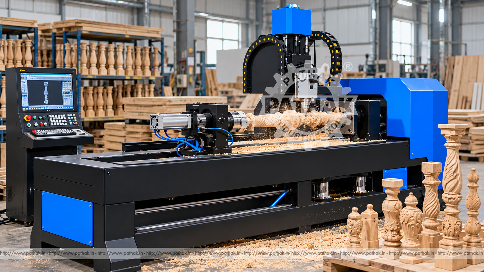
Decorative wooden components often combine a symmetrical turned profile with flutes, grooves, relief patterns, or details that do not repeat evenly around the centreline. Producing those forms manually requires skill and considerable time, while moving the work between separate turning and carving stations can introduce alignment errors. A 4 Axis CNC Wood Turning Lathe Carving Machine brings controlled rotation and programmed tool movement together for repeatable woodworking.
The Pathak Industries KCP-CWT 4 is intended for shaped wood components such as staircase columns, balusters, furniture legs, posts, decorative rails, and similar elongated work. Its published specification lists a 1500 mm length by 300 mm diameter working area when one spindle is used, a 4 kW servo spindle motor with variable-speed belt drive, four-axis DSP control, precision screw-driven feeding, and a limit-alarm arrangement intended to help prevent collisions. This guide explains how those features support production without assuming capabilities beyond the selected configuration.
A conventional wood lathe rotates a blank while a cutting tool shapes its outer surface. That method is excellent for round and symmetrical forms, but decorative production may also require indexed patterns, spiral details, flutes, and relief carving. A four-axis CNC wood lathe coordinates the rotating workpiece with controlled linear tool movement, allowing a programmed design to be reproduced across multiple parts.
The machine is not simply a manual lathe fitted with a display. The control system, feed mechanism, spindle drive, workholding, toolpath, and machine structure operate as a coordinated system. The result depends on correct programming, sound timber, suitable cutters, secure support, and realistic cutting parameters.
A prepared wooden blank is mounted between the driving and supporting points. The setup establishes the component centreline and ensures that the stock can rotate without striking the tool, supports, or machine structure. Once the zero position and program are confirmed, the spindle rotates the work while the cutting unit follows the programmed path.
For a normal turned section, coordinated longitudinal and radial movement generates the required diameter and contour. When the design contains non-symmetrical decoration, controlled angular positioning allows the cutter to address selected areas around the part. The four-axis arrangement therefore expands the range of shapes that can be organised in one programmed workflow.
Before full production, a new program should be checked above the work or with a safe reduced approach. Operators should verify direction, clearances, tool length, stock allowance, rotation, and limit positions. A controlled first-piece process is especially important when a design contains deep relief or rapid changes in diameter.
The listed working area is 1500 mm in length by 300 mm in diameter when operating with one spindle. These figures provide a starting point for selecting jobs, but usable capacity also depends on the actual blank, chucking or centre arrangement, tool reach, tail support, cutter clearance, and programmed profile.
A rough square blank requires more rotational clearance than its finished diameter suggests. Long slender parts may also need conservative cutting forces to control vibration. Buyers should therefore assess the largest raw blank and the most demanding feature, not only the finished component dimensions.
The published configuration identifies a 4 kW servo motor with a variable-frequency spindle arrangement and belt-type drive. Servo control supports coordinated rotation, while variable speed helps match spindle behaviour to the work diameter, timber, tool, and operation. The belt arrangement is also described as accessible for replacement.
Correct speed is determined by more than the motor rating. Large or unbalanced blanks generally demand a cautious starting speed. Cutting should begin only after the blank has been inspected for cracks, weak knots, foreign objects, and secure mounting. Speed can then be established according to the approved process and observed machine behaviour.
The product data describes combined guide rails with precision screw drive for the feed system. These elements guide the tool along its programmed route. Clean rails, correct lubrication, properly maintained drive components, and controlled acceleration all contribute to repeatable positioning and surface quality.
The overall machine is described as stable and low-inertia. In practice, installation still matters. A level, suitably prepared foundation and correct machine anchoring help keep motion predictable. Loose workholding, a worn cutter, an unsupported blank, or an unstable floor can reduce finish quality even when the programmed coordinates are correct.
The KCP-CWT 4 lists an original DSP control system supporting four axes. A dedicated controller gives the operator a structured way to load programs, set references, position axes, and supervise a cycle. The exact file preparation and transfer workflow should follow the machine documentation supplied with the selected unit.
Program management deserves the same discipline as physical setup. Files should have clear part numbers and revision status. Proven programs should be protected from unapproved editing, and any tool or stock change should trigger a new setup check. A CNC machine repeats instructions consistently, including incorrect ones, so controlled revisions are essential.
The published specification describes a turning centre arrangement, manual tail-pin extension combined with pneumatic assistance, and a single lathe tool post in the listed configuration. Tail support helps locate and stabilise suitable elongated blanks. Its alignment and contact pressure must be checked so the wood is supported without being crushed or displaced.
Cutter geometry should match the operation and wood species. Sharp tools reduce cutting load and limit tearing. The holder must secure the cutter at the approved projection, because unnecessary overhang encourages vibration. Tool length and diameter must also agree with the program offsets before a cycle starts.
A four-axis CNC wood turning and carving machine can support manufacturers producing repeated decorative and functional components, including:
Suitability must be confirmed from the real drawing, wood type, blank size, required finish, feature depth, and expected output. Very delicate, highly irregular, or oversized work may require a different holding method or machine arrangement.
Once a program, tool, blank, and setup are validated, the same motion can be repeated. This is useful when matching balusters or furniture parts must share consistent proportions and decorative placement.
Programmed coordinates reduce the need to mark every contour and decorative position by hand. Operators still inspect dimensions and finish, but the machine provides a repeatable motion reference.
Coordinated rotation and cutter movement can organise round profiling and selected carved details in a common setup. Fewer transfers can help preserve alignment and reduce handling, depending on the component.
Digital programs make it practical to retain multiple approved designs and return to them when repeat orders arrive. Design changes should still pass through drawing review, toolpath verification, and first-piece inspection.
Reliable machining starts before the blank reaches the machine. Timber should be appropriately seasoned, reasonably straight, and free from defects that could compromise safe rotation. The rough section must leave enough material for the finished profile while remaining within the machine's rotational clearance.
The digital model or drawing should identify finished diameters, lengths, transitions, carved regions, and areas reserved for holding. Toolpaths need suitable roughing and finishing allowances. An efficient program removes stock progressively instead of forcing a finishing cutter to remove excessive material in one pass.
Wood grain changes direction around knots and figured areas, so surface quality can vary even when geometry is correct. Sharp cutters, stable stock, suitable feed, appropriate spindle speed, and well-planned cutting direction help limit torn grain and chatter. Light finishing passes may improve the surface before sanding or coating.
Inspection should use consistent reference points. Diameters can be checked at defined stations, while templates or profile gauges can help compare complex contours. Decorative alignment, total length, end allowances, and matching appearance should be included in the first-piece record.
Wood turning and carving create chips and fine dust. The workspace needs an appropriate extraction and housekeeping plan suited to the material and production volume. Accumulated dust should not obstruct rails, screws, sensors, ventilation openings, or electrical equipment.
Only trained personnel should operate or service the machine. Guards and protective systems must remain in their intended positions. Operators should keep clear of rotating stock and moving axes, use suitable personal protective equipment, and isolate all energy before tool changes or maintenance. The listed limit-alarm system is a useful protective feature, but it does not replace correct programming, guarding, or supervision.
At the start of a shift, remove chips safely and inspect the cutter, holder, work centres, belt condition, guards, cables, hoses, and emergency controls. Check the guide and screw-drive areas for contamination and follow the prescribed lubrication schedule. Unusual sound, vibration, heat, or positioning behaviour should be investigated before production continues.
Periodic maintenance should include alignment checks, fastener inspection, drive adjustment, electrical enclosure cleaning, pneumatic system checks where fitted, and verification of reference accuracy. Maintenance records help identify recurring wear and allow service to be planned before output or quality is affected.
Begin with representative component drawings and raw blanks. Confirm maximum stock length and rotating diameter, minimum detail size, relief depth, timber species, required finish, batch quantity, and production target. Then compare those needs with the working envelope, spindle arrangement, tool access, controller, feed system, support method, extraction provisions, and available factory space.
Utilities, operator skills, tooling, programming workflow, installation, training, and service access should be evaluated along with machine capacity. Pathak Industries can review application details against the selected configuration, but the final choice should be based on actual samples and documented requirements.
The product page lists a 1500 mm length by 300 mm diameter working area when one spindle is used. Actual suitability also depends on raw-stock clearance, holding, tool reach, and the programmed profile.
It coordinates controlled tool movement with workpiece rotation, supporting conventional turned profiles as well as selected indexed or carved details around the component.
The published configuration specifies a 4 kW servo motor with variable-frequency control and a belt-type drive. Operating parameters must be selected for the blank, timber, cutter, and approved process.
Yes, staircase columns and similar decorative elongated components are representative applications, provided their blank dimensions and designs fit the confirmed working range.
An approved program can be retained for repeat work, but the tool, offsets, blank size, mounting, and program revision should be verified whenever production restarts.
No. Operators still need training in workholding, tool selection, program verification, safe proving, inspection, and recognising abnormal machine behaviour.
Provide drawings or samples, raw and finished dimensions, wood type, decorative features, batch volume, finish expectations, utilities, available space, and any required tooling or extraction arrangement.
Keep the machine free of chips and dust, inspect tools and work supports, maintain rails and screw drives according to the schedule, check belts and safety devices, and isolate energy before service.
The Pathak Industries KCP-CWT 4 combines controlled wood turning with four-axis carving capability for repeat decorative component production. Its stated 1500 by 300 mm single-spindle working area, servo-driven spindle, precision feed arrangement, DSP control, and limit alarm provide a practical foundation for suitable furniture and architectural wood parts. Careful application review, sound blanks, validated programs, sharp tooling, disciplined inspection, and preventive maintenance remain the keys to productive operation.