
Head Office
117, Grand Trunk Road, Salkia Howrah-700013, Kolkata, India
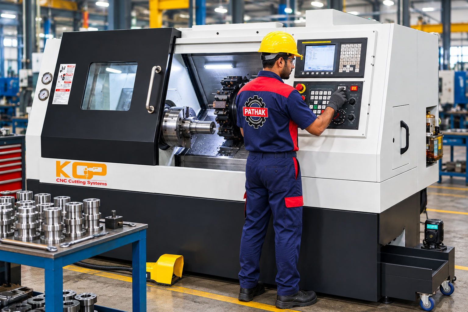
Modern manufacturing increasingly depends on accuracy, repeatability, productivity, and process control. Components that once required continuous manual adjustment on conventional lathes can now be produced through programmed machining cycles using CNC technology.
Modern manufacturing increasingly depends on accuracy, repeatability, productivity, and process control. Components that once required continuous manual adjustment on conventional lathes can now be produced through programmed machining cycles using CNC technology.
A CNC Lathe Machine (Computer Numerical Control Lathe) is an automated machine tool primarily used to manufacture rotational components. The workpiece is securely held and rotated by the spindle while cutting tools remove material according to programmed coordinates, feeds, speeds, and machining sequences.
CNC lathes can perform operations such as turning, facing, taper turning, grooving, threading, boring, drilling, parting, chamfering, and profile machining, depending on the machine configuration and tooling.
The machine range covered in this article includes:
The supplied reference images show enclosed CNC turning machines with integrated operator controls, chucks, multi-tool arrangements or turrets, and guarded machining areas. Exact capacities and specifications should be taken from the technical data for each individual model rather than inferred from appearance alone.
A CNC lathe is a computer-controlled turning machine designed to remove material from a rotating workpiece.
In a basic turning operation, the workpiece rotates around its axis while a cutting tool moves along programmed paths. The CNC controller coordinates machine movement to create the required diameter, length, profile, groove, thread, bore, or other feature.
Instead of relying on the operator to continuously manipulate handwheels, the CNC system executes a prepared machining program.
A typical CNC turning program can control parameters such as:
This makes CNC lathes particularly valuable for repetitive manufacturing and components requiring consistent dimensional control.
Production starts with the component drawing or CAD model. The manufacturer determines the raw material, starting diameter, finished dimensions, tolerances, surface finish requirements, required machining operations, cutting tools, workholding, and inspection requirements.
The machining instructions are converted into a CNC program. Depending on the manufacturing environment, programming may be performed manually using G-code and machine cycles or prepared using suitable CAD/CAM software.
The program defines how the machine and cutting tools should move during production.
The raw material or component is loaded into the machine and securely clamped in the chuck or another appropriate workholding system. Correct clamping is critical for machining accuracy and operator safety.
Required cutting tools are installed in the machine's tool-holding system. Depending on the operation, tooling can include:
Tool offsets must be correctly established before production.
Before full production, the operator should verify the program, tool positions, offsets, workpiece setup, clearances, spindle direction, and machining sequence.
A dry run, simulation, single-block operation, or other machine-approved verification method can help identify programming or setup problems before machining begins.
Once the setup has been verified, the CNC system controls the machining sequence. The spindle rotates the workpiece while the selected cutting tools move along the programmed X and Z coordinates.
The first finished component should be measured against the drawing. Typical checks include:
After the first component is approved, production can continue with an appropriate inspection schedule.
Turning reduces or controls the outside diameter of a rotating component. It is one of the principal operations performed on CNC lathes.
Facing machines the end of the workpiece to produce a flat surface and establish an accurate length reference.
Different diameters are machined along the same component to produce stepped shafts and similar parts.
The tool follows a programmed angular path to produce a tapered surface.
Boring enlarges or accurately finishes an existing internal hole.
Suitable drilling tools can be positioned along the spindle axis to produce holes in the rotating workpiece.
CNC control allows synchronized spindle rotation and tool movement for producing accurate threads. Depending on tooling and machine capability, both external and internal threads can be machined.
A grooving tool produces controlled recesses on external or internal surfaces.
Parting tools are used to separate a finished component from bar stock or remove a section of material.
Chamfers remove sharp edges and can prepare components for assembly or subsequent operations.
CNC-controlled movement can create more complex contours than simple straight or stepped turning.
The CNC Lathe Machine KGP 60 provides a compact CNC turning solution for suitable precision machining applications.
Based on the supplied reference image, the machine features a substantially enclosed working area and an integrated CNC control panel. Its compact configuration can be useful where manufacturers need CNC turning capability while managing available production-floor space.
The exact chuck size, spindle bore, turning diameter, turning length, spindle power, axis travel, tooling capacity, and accuracy should be specified according to the KGP 60 technical datasheet.
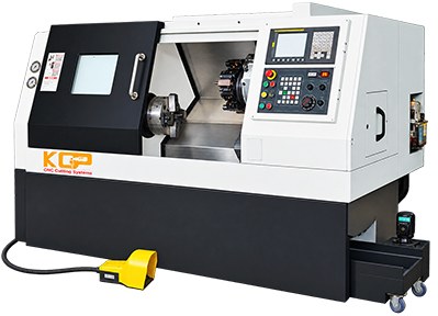
The CNC Lathe Machine KCP 300 is designed for turning rotational components and producing faces, diameters, bores, or threads...
View Product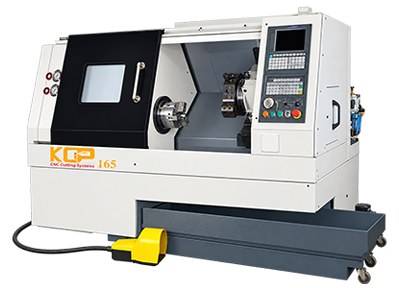
The CNC Lathe Machine KGP 165 handles shafts, bushes, sleeves, discs, and other title-specific round parts through a layout i...
View Product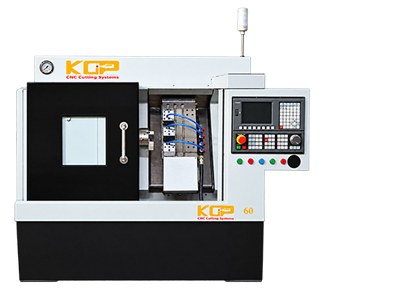
The primary role of the Cnc Lathe Machine KGP 60 is turning rotational components and producing faces, diameters, bores, or t...
View ProductMachine suitability should always be confirmed against the actual component drawing and technical specification.
The CNC Lathe Machine KGP 165 can serve manufacturers requiring a more substantial CNC turning platform for industrial component production.
The supplied reference image shows an enclosed machining area, chuck, multi-position tooling arrangement, CNC operator panel, and foot-operated control equipment.
This type of configuration supports a production-oriented workflow where multiple turning operations can be incorporated into a programmed machining sequence.
The CNC Lathe Machine KCP 300 represents another enclosed CNC turning configuration within the range.
The supplied machine reference shows an enclosed working zone, chuck/workholding arrangement, multi-tool turret-type configuration, integrated CNC control panel, and a robust machine enclosure.
The exact machining capacity of the KCP 300—including maximum turning diameter, turning length, spindle bore, spindle speed, motor power, turret configuration and axis travels—should be obtained from its actual technical specification.
For manufacturers handling repeat jobs, a correctly configured CNC lathe can reduce manual intervention while improving control over machining sequences and component dimensions.
The three machines should not be compared solely according to their model numbers. A buyer should compare their actual technical specifications and intended component range.
| Selection Factor | KGP 60 | KGP 165 | KCP 300 |
|---|---|---|---|
| CNC turning | Yes | Yes | Yes |
| Enclosed machining area | Shown in reference | Shown in reference | Shown in reference |
| Integrated CNC control | Shown in reference | Shown in reference | Shown in reference |
| Precision component production | Suitable | Suitable | Suitable |
| Repetitive manufacturing | Suitable | Suitable | Suitable |
| Turning capacity | Check specification | Check specification | Check specification |
| Spindle bore | Check specification | Check specification | Check specification |
| Tool capacity | Check specification | Check specification | Check specification |
| Axis travel | Check specification | Check specification | Check specification |
| Motor power | Check specification | Check specification | Check specification |
The final machine should be selected according to workpiece size, material, complexity, required accuracy, production volume and actual machine specifications.
Depending on machine capability, cutting tools, speeds, feeds and process requirements, CNC lathes can machine a wide range of engineering materials.
Not every material should be machined using identical parameters. Cutting speed, feed, depth of cut, tool material, insert geometry and coolant strategy should be selected according to the actual workpiece material.
CNC lathes can manufacture shafts, bushes, sleeves, hubs, pins, threaded components, spacers and numerous other rotational automotive parts.
Engineering workshops use CNC turning for both custom and repetitive components.
Hydraulic systems require accurately machined components such as bushes, sleeves, adapters, fittings, glands, pistons and other turned parts.
Tractors and agricultural equipment use numerous shafts, pins, bushes, spacers and threaded components.
CNC turning is used to manufacture components for lathes, milling machines, drilling machines, presses and other industrial equipment.
Suitable pump and valve components can require turning, boring, facing, grooving and threading operations.
Rotational and cylindrical components used in motors, generators and industrial electrical equipment can require precision turning.
CNC turning can be used for suitable shafts, bushes, sleeves, pins and other railway-related engineering components.
Earthmoving and construction machinery contain many precision-turned hydraulic and mechanical components.
CNC turning is also used for suitable high-precision components where process control, material traceability and dimensional inspection requirements are especially demanding.
Once a program, tooling and setup have been validated, the machine can reproduce the same programmed movements for subsequent components. This makes CNC turning highly suitable for batch and production manufacturing.
CNC-controlled axis movements enable manufacturers to machine components according to programmed dimensions and tool offsets. Actual finished accuracy still depends on machine condition, tooling, workholding, material, thermal effects and process control.
Multiple machining operations can be incorporated into a programmed cycle, reducing the amount of continuous manual intervention required.
CNC programming makes it practical to machine combinations of diameters, tapers, grooves, threads, radii and profiles within a coordinated sequence.
Saved programs can be reused for repeat orders, subject to verification of tooling, offsets, workholding and material.
Controlled machine movements help manufacturers maintain process consistency across production batches.
A skilled operator is still essential for setup, tooling, programming, inspection and troubleshooting, but the CNC system automates much of the repetitive axis movement during the machining cycle.
The same machine can manufacture many different components by changing the program, tooling, workholding and raw material.
| Requirement | Conventional Lathe | CNC Lathe |
|---|---|---|
| Axis movement | Primarily operator controlled | Program controlled |
| Repeat production | Operator dependent | Highly repeatable when properly set |
| Complex profiles | More difficult | Easier through programming |
| Batch production | Suitable | Highly suitable |
| Program storage | No conventional CNC program | Yes |
| Tool movement | Manual/semi-automatic depending on machine | CNC controlled |
| Setup skill | Required | Required |
| CNC programming | Not required | Required |
| Prototype work | Excellent | Excellent when programmed efficiently |
| High-volume repetitive turning | More labor intensive | Well suited |
Both machine types remain valuable. The correct choice depends on production requirements rather than assuming CNC is necessary for every turning job.
Start with the largest component you expect to machine. Check both the raw stock diameter and the finished component diameter. Compare these dimensions with the machine's specified turning capacity.
Identify the longest component in your production range. Verify the machine's applicable turning length and workholding arrangement.
Spindle bore becomes particularly important when machining components from bar stock. A larger through-bore can allow larger-diameter bar material to pass through the spindle, subject to the machine's specified capacity.
Determine whether you primarily machine mild steel, stainless steel, alloy steel, aluminium, brass, cast iron, engineering plastics, or other materials. Material affects spindle power requirements, tooling, cutting parameters and productivity.
List every operation required for your components:
Review the engineering drawing and identify dimensional tolerances, geometric tolerances, surface-finish requirements, concentricity requirements, and thread tolerances. Select the machine and manufacturing process accordingly.
If a component requires several different operations, sufficient tooling positions can reduce manual tool changes. Check the actual tool-holding or turret configuration of the machine.
Large steel components and small aluminium parts can require very different machining conditions. Evaluate the spindle speed range, torque characteristics and motor power against your production requirements.
Important factors can include:
For prototype and small-batch work, quick setup and programming flexibility can be particularly important. For high-volume production, cycle time, tool life, chip control, automation and material handling become increasingly significant.
Understand all dimensions, tolerances, materials, threads and surface requirements before programming.
Select material of the correct grade and starting dimensions.
Choose a suitable chuck, jaws, collet, fixture or other approved workholding arrangement.
Choose appropriate tools and inserts for the material and operations.
Create the required machining sequence with suitable speeds, feeds and tool movements.
Accurate offsets are essential because the CNC controller uses them to determine tool positions relative to the component.
Check tool clearance, workholding, program coordinates, spindle direction and other critical parameters.
Use the machine manufacturer's recommended verification procedures before running at full production conditions.
Measure all critical dimensions. Do not begin full batch production until the component meets the required specification.
Periodically inspect components and monitor tool wear, chip formation, surface finish and machine condition.
The workpiece must be securely and concentrically held. Incorrect clamping can cause dimensional errors, vibration and poor surface finish.
Cutting tools gradually wear during machining. Tool offsets should be monitored and adjusted according to the approved production procedure.
Excessive speed, feed or depth of cut can reduce tool life and adversely affect component quality. Parameters should match the workpiece material, tool and operation.
Machining generates heat that can affect the cutting tool, workpiece and dimensional stability. Use the appropriate cutting strategy and coolant or lubrication where required.
Excessive tool overhang can increase vibration and reduce rigidity.
Use appropriate measuring equipment such as:
Manufacturers can improve CNC turning productivity by focusing on the complete process rather than simply increasing spindle speed.
The fastest cutting parameters do not necessarily provide the lowest production cost. Tool life, component quality, machine load and scrap rate must also be considered.
Preventive maintenance helps maintain machine reliability, accuracy and service life. Maintenance should follow the machine manufacturer's schedule and can include inspection of:
The machine should also be kept clean, particularly around the machining area and chip-management system.
CNC automation does not eliminate machining hazards. Rotating workpieces, chucks, cutting tools, sharp chips, coolant, automatic tool movements and stored energy can create serious hazards.
Operators should:
Safe machining always takes priority over cycle-time reduction.
CNC Lathe Machines combine computer-controlled automation with precision turning technology to manufacture rotational components efficiently and consistently. From simple bushes and pins to shafts, hubs, flanges, threaded components and complex profiles, CNC turning supports an extensive range of industrial production requirements.
The CNC Lathe Machine KGP 60 can provide a compact CNC turning solution for suitable precision components and workshop applications. The CNC Lathe Machine KGP 165 can address broader industrial turning and repetitive component production requirements, while the CNC Lathe Machine KCP 300 provides another production-oriented CNC turning configuration for suitable industrial components.
Rather than selecting a machine based only on model designation, manufacturers should evaluate maximum turning diameter, turning length, spindle bore, spindle speed and power, chuck size, tooling capacity, axis travels, controller, component complexity, material, accuracy requirements and expected production volume.
With appropriate programming, rigid workholding, suitable cutting tools, optimized machining parameters, systematic inspection and preventive maintenance, CNC lathe machines can provide a highly productive foundation for modern precision manufacturing.