Head Office
117, Grand Trunk Road, Salkia Howrah-700013, Kolkata, India
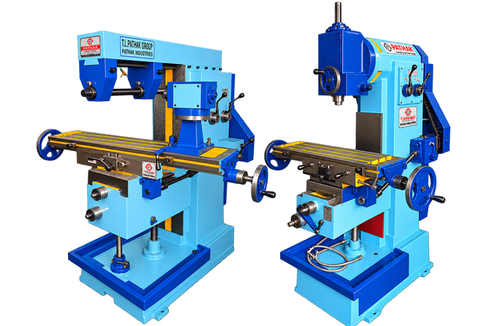
The Universal and Vertical Milling Machine is designed for machining faces, slots, keyways, and contoured features. The operating method supports tool rooms, maintenance departments, and component factories and centres on controlled table travel and rigid cutter support. The vertical arrangement affects loading, support, and access to the work.
Shipping Information Usually dispatched With In business days
For facilities needing machining faces, slots, keyways, and contoured features, the Universal and Vertical Milling Machine offers a process-specific workstation. Its arrangement supports machine parts, dies, fixtures, and repair components while keeping the important operating area accessible.
The machine is applicable to tool rooms, maintenance departments, and component factories. It can support individual jobs, recurring batches, or a dedicated station between earlier preparation and later inspection.
A typical cycle begins with locating the job correctly, after which the machine feeds supported work against a rotating multi-edge cutter. Its controlled table travel and rigid cutter support supports repeat work without replacing the need for trained operation. The vertical arrangement affects loading, support, and access to the work.
When comparing versions of the Universal and Vertical Milling Machine, buyers should review the work envelope, tooling, control method, loading, and service access. Numerical capacity, speed, accuracy, or power must be confirmed from the selected model’s documented specification.
Pathak is a Manufacturer, Supplier and Exporter offering this machine with application-based product guidance.
| MODEL | PM OA | PM 1 | PM 1.5 | PM 2 | PM 3 | PM 4 |
| Face of Body | 6.5" | 8.5" | 10" | 11" | 12" | 13" |
| Surface Table | 30"*7" | 40"*9" | 48"*10" | 51"*11" | 58"*12" | 64"*13" |
| No. of T - Slots | 3 | 3 | 3 | 3 | 3 | 3 |
| Size of T - Slots | 3/8" | 1/2" | 1/2" | 1/2" | 5/8" | 5/8" |
| Swivel either side of center | 45 dgr | 45 dgr | 45 dgr | 45 dgr | 45 dgr | 45 dgr |
| Cross | 6" | 7" | 8" | 10" | 12" | 13" |
| Vertical of Traverse | 12" | 13" | 16" | 22" | 24" | 26" |
| Longitudinal Traverse | 14" | 19" | 22" | 25" | 28" | 30" |
| Standard Abour Dia | 1" | 1" | 1" | 1" | 1" | |
| Taper of Spindle | ISO 30 | ISO 40 | ISO 40 | ISO 40 | ISO 40 | ISO 40 |
| No. of Spindle Speed | 3 & 6 | 6 & 9 | 6 & 9 | 6 & 9 | 6 & 9 | 6 & 9 |
| Range of Spindle Speed | 45 to 550 | 45 to 550 | 50 to 750 | 80 to 680 | 42 to 700 | 42 to 700 |
| Dia of Spindle | 2" | 2.5" | 2.3/4" | 3.1/4" | 3.1/2" | 3.5/8" |
| No. of Longitudinal Feed Table | 2 | 2 | 2 | 2 | 3 | 3 |
| H.P | 1 | 2 | 2 | 2 | 3 | 5 |
| Floor Space (Base) | 26"*17" | 35"*20" | 40"*24" | 46"*26" | 48"*28" | 56"*30" |
| Height | 55" | 62" | 67" | 70" | 73" | 75" |
| Weight (Approx) | 500 kg. | 1100 kg. | 1450 kg. | 2200 kg. | 2750 kg. | 3650 kg. |