Head Office
117, Grand Trunk Road, Salkia Howrah-700013, Kolkata, India
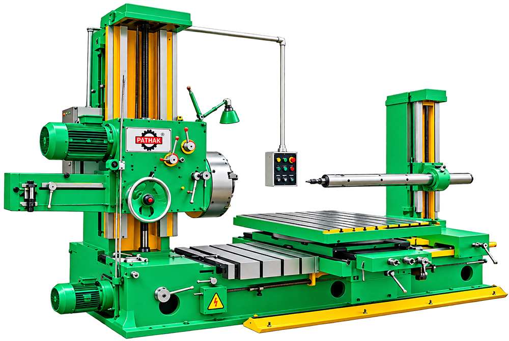
For work involving castings, housings, cylinders, and machine parts, the Horizontal Boring Machine offers a process-specific solution. The operating method supports machine shops, engine repair, and heavy maintenance and centres on rigid spindle guidance for internal machining. The horizontal layout supports work along a level machine axis.
Shipping Information Usually dispatched With In business days
The Horizontal Boring Machine provides a dedicated method of enlarging and correcting existing holes. Rather than acting as unrelated general equipment, it brings the working elements together around castings, housings, cylinders, and machine parts.
A typical cycle begins with locating the job correctly, after which the machine positions a boring tool accurately within the supported component. Its rigid spindle guidance for internal machining supports repeat work without replacing the need for trained operation. The horizontal layout supports work along a level machine axis.
Likely users are found in machine shops, engine repair, and heavy maintenance. They may use it to organise the named operation, reduce repeated handling, and establish a consistent workstation for suitable jobs.
Selection should follow the real workpiece, material, operation, production frequency, handling method, and available space. Exact performance data must come from the technical specification for the chosen Horizontal Boring Machine.
Pathak is a Manufacturer, Supplier and Exporter offering this machine with application-based product guidance.
| MODEL | PHB-65 | PHB-80 | PHB-100 | PHB-110 | PHB-125 |
| Alloy Steel Work Spindle Hardened & Ground - Diameter | 65 | 80 | 100 | 110 | 125 |
| MorseTaper Number | 4 | 5 | 6 | 6 | 6 |
| Max.Longitudinal Movements of Working Spindle | 410 | 510 | 510 | 600 | |
| Number of Spindle Speeds | 9 | 9 | 9 | 9 | 9 |
| Range of Spindle Speeds - R.P.M. | 20 to 300 | 15 to 300 | 15 to 300 | 15 to 250 | 15 to 250 |
| Longitudinal Work Spindle Feeds Nos. | 9 | 9 | 9 | 9 | 9 |
| Max.Height of The Spindle Axis from Table Surface | 800 | 925 | 1000 | 1100 | 1200 |
| Min.Height of The Spindle Axis from Table Surface | 20 | 25 | 30 | 30 | 30 |
| Dimensions of The Rotary Table | 840 x 1050 | 900 x 1105 | 1030 x 1375 | 1100 x 1450 | 1220 x1675 |
| Longitudinal Table Traverse | 1500 | 1625 | 1725 | 1925 | 2050 |
| Long.Table Traverse Feeds (Including one Rapid) | 10 | 10 | 10 | 10 | 10 |
| Transversal Table Travel Feeds (Including one Rapid) | 10 | 10 | 10 | 10 | 10 |
| Vertical Head Stock Travel Feeds Including one Rapid | 4 | 4 | 4 | 4 | 10 |
| Rotary Table Automatic Feeds (Including one Rapid) | Nil | 10 | 10 | 10 | 10 |
| Max.Cross Movement of The Table | 910 | 1000 | 1100 | 1300 | 1500 |
| Max.Distance between Stay Bearing & Facing Head | 2150 | 2400 | 2690 | 2800 | 2950 |
| Facing Head Diameter | 450 | 505 | 555 | 600 | 650 |
| Weight Approximate in kgs. (With packing & Accessories) | 7500 | 9500 | 11500 | 14500 | 18000 |
| Weight Approximate in kgs. (Without packings Accessories) | 7000 | 8500 | 9500 | 11000 | 13500 |
| Power Motor (HP) | 3 & 1.5 | 5 & 2 | 7.5 & 2 | 10 & 3 | 12.5 & 5 |