Head Office
117, Grand Trunk Road, Salkia Howrah-700013, Kolkata, India
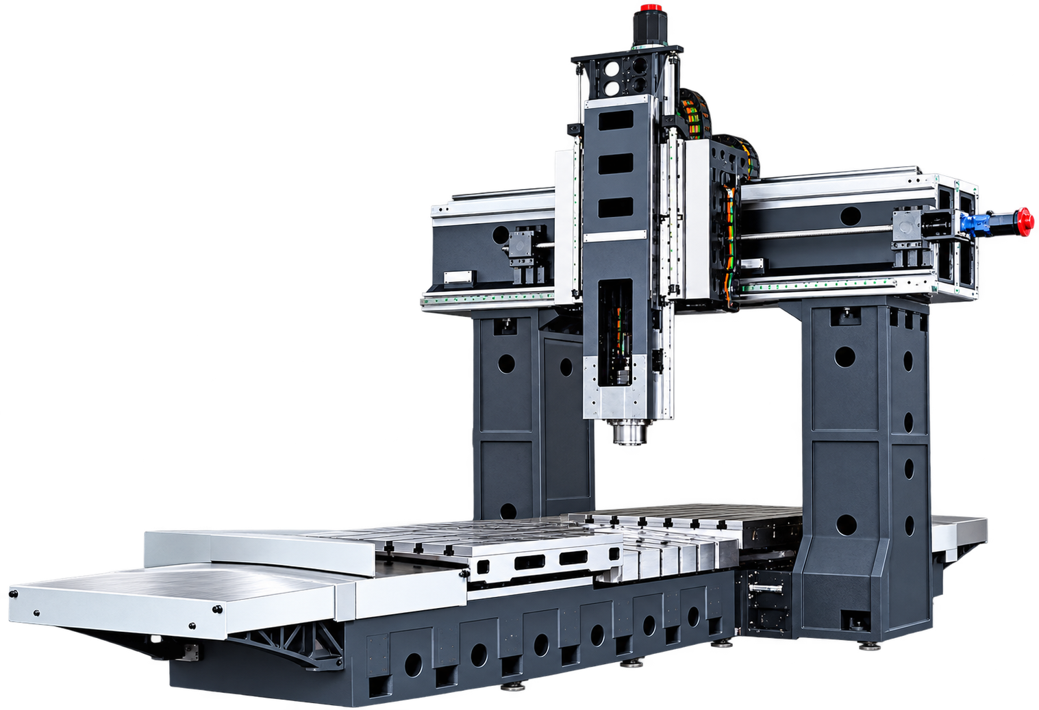
A rigid gantry-style machining platform for large dies, plates, frames and precision components. Four PGMC models provide X-axis travel from 1600 to 2500 mm, table loads up to 6000 kg and 24-tool capacity.
Shipping Information Usually dispatched With In business days
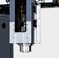
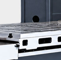
The Gantry Machining Center is designed for machining large workpieces within a rigid bridge-type structure. Twin columns support the cross rail and spindle assembly around the working area, helping maintain tool positioning across wide components while keeping the work securely located on the table.
The PGMC range includes PGMC1611, PGMC2013, PGMC2016 and PGMC2518 models. Listed X-axis travels extend from 1600 to 2500 mm, Y-axis travels from 1100 to 1800 mm and Z-axis travels from 600 to 850 mm. Table sizes and gantry widths increase across the range to accommodate different component envelopes.
Depending on the model, the table supports listed loads from 1600 to 6000 kg. Spindle speeds are listed at 8000 rpm for PGMC1611, PGMC2013 and PGMC2016, and 6000 rpm for PGMC2518. Every model lists a 24-tool capacity, supporting multi-operation machining with reduced manual tool changes.
Typical applications include machining dies and mould bases, plates, machine frames, fabricated structures, energy and transport components, and other large parts requiring milling, drilling, boring, contouring or related operations. Final model selection should consider the full workpiece and fixture envelope, total load, required travels, gantry clearance, tool reach, spindle requirements, tolerance, surface finish, material-removal rate, chip management and installation foundation.
| Parameter | Unit | PGMC1611 | PGMC2013 | PGMC2016 | PGMC2518 |
|---|---|---|---|---|---|
| X-Axis Travel | mm | 1600 | 2000 | 2100 | 2500 |
| Y-Axis Travel | mm | 1100 | 1300 | 1630 | 1800 |
| Z-Axis Travel | mm | 600 | 600 | 700 | 850 |
| Spindle Center to Table | mm | 190-740 | 140-740 | 150-850 | 200-1050 |
| Gantry Width | mm | 1100 | 1300 | 1650 | 1800 |
| Table Size | mm | 1600 x 900 | 2000 x 1000 | 2200 x 1400 | 2500 x 1500 |
| T-Slots | mm | 7-18-125 | 5-18-140 | 7-22-170 | 9-22-185 |
| Max. Table Load | kg | 1600 | 2000 | 4000 | 6000 |
| Spindle Speed | rpm | 8000 | 8000 | 8000 | 6000 |
| Spindle Power | kW | 11 | 11/15 | 15/18.5 | 18.5/22 |
| Source Row Label: 3-Phase Motor | - | BT40-BT50 | BT40-BT50 | BT40-BT50 | BT50-190 |
| XYZ Rapid Feed | m/min | 18/18/15 | 18/18/15 | 15/15/12 | 10/10/8 |
| Tool Capacity | pcs | 24 | 24 | 24 | 24 |
| Overall Size | mm | 4680 x 3300 x 1200 | 6000 x 3550 x 4200 | 6000 x 3800 x 4350 | 6800 x 4200 x 4500 |
| Machine Weight | kg | 11000 | 12000 | 17000 | 22000 |
Note: The supplied specification image labels the BT40/BT50 values as “3-phase motor.” Confirm the intended parameter and final spindle interface with the technical quotation.