Head Office
117, Grand Trunk Road, Salkia Howrah-700013, Kolkata, India
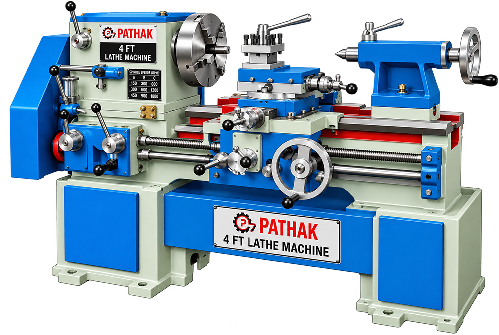
For work involving shafts, bushes, sleeves, discs, and other title-specific round parts, the 4 FT Lathe Machine offers a process-specific solution. Its rigid workholding with controlled tool travel suits machine shops, repair workshops, tool rooms, and component plants.
Shipping Information Usually dispatched With In business days
The 4 FT Lathe Machine is a purpose-built unit for turning rotational components and producing faces, diameters, bores, or threads. Its layout is organised around shafts, bushes, sleeves, discs, and other title-specific round parts, making it relevant when this operation must be completed in a controlled sequence.
In operation, it rotates a securely held workpiece while a guided tool removes material. The practical focus is rigid workholding with controlled tool travel. Correct workholding, tooling, supervision, and routine inspection remain important because results depend on the material and setup.
Natural settings include machine shops, repair workshops, tool rooms, and component plants. There the machine may serve production, repair, preparation, assembly, finishing, or testing according to its title and the surrounding workflow.
Machines within lathe machines can differ in arrangement and capability. The required 4 FT Lathe Machine should therefore be matched to actual samples or process details, with tooling, controls, guarding, and utilities verified before ordering.
Pathak is a Manufacturer, Supplier and Exporter offering this machine with application-based product guidance.
| MODEL | HL-4 | HL-6 | HL-8 | HL-10 | HL-12 | HL-16 | HL-20 |
|---|---|---|---|---|---|---|---|
| LENGTH OF BED | 4′-6″ | 6′-0″ | 8′-0″ | 10′-0″ | 12′-0″ | 16′-0″ | 20′-0″ |
| WIDTH OF BED | 12” | 14” | 16” | 18” | 20” | 22” | 22” |
| CENTRE FROM BED | 10″ | 12″ | 14″ | 16″ | 19″ | 20″ | 20″ |
| WIDTH OF GAP | 5″ | 9″ | 12″ | 14″ | 19″ | 19″ | 19″ |
| SWING OVER SADDLE (dia) | 10″ | 16″ | 21″ | 24″ | 26″ | 30″ | 30″ |
| SWING IN GAP (dia) | 28″ | 36″ | 41″ | 47″ | 54″ | 60″ | 60″ |
| ADMIT BETWEEN CENTRES | 2′-3″ | 3′-0″ | 4′-6″ | 5′-8″ | 7′-6″ | 11′-0″ | 11′-0″ |
| HOLLOW SPINDLE | 1.3/4″ | 2.1/8″ | 3.1/8″ | 3.5/8″ | 4.1/8″ | 4.1/8″ | 4.1/8″ |
| NO. OF SPINDLE SPEEDS | 6 | 6 | 6 | 6 | 6 | 6 | 6 |
| Dia. OF LEADSCREW | 1.3/8″ | 1.5/8 | 1.5/8 | 1.1/2″ | 1.3/8″ | 1.3/4″ | 1.3/4″ |
| Dia. OF FEEDSHAFT | 1″ | 1.1/8″ | 1.1/8″ | 1.3/8″ | 1.3/8″ | 1.3/8″ | 1.1/2″ |
| POWER REQUIRED | 1 H.P | 2 H.P | 3H.P | 3H.P | 5H.P | 5H.P | 7.5H.P |
| R.P.M OF MOTOR (APPROX) | 1440 | 1440 | 960 | 1440 | 1440 | 1440 | 960 |
| NETT WEIGHT (APPROX) | 800 Kgs | 1200 Kgs | 1800 Kgs | 2300 Kgs | 2800 Kgs | 4200 Kgs | 5200 Kgs |