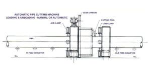
Automatic Pipe Cutting Machine Loading & Uploading Manual or Automatic
₹1,665,000.00
In Stock
Automatic Pipe Cutting Machine is available in two version. In the simpler version. the pipe is placed on to the roller of in feed conveyor and is pushed manually till it touches the stopper. The Start button is pressed which clamps the idler pipe and a cutting tool moves round the pipe to complete the parting operation and the pipe is uploaded manually.In the advanced version, the pipes are placed on the rack from where it is loaded one by one to the infeed conveyor, which conveys the pipes to the cutting station for parting the pipes to the predetermined length and is unloaded from the outfeed conveyor.
Idler Testing Equipment is supplied for testing of the idler after assembly. Dust proof testing is done in a chamber where the idler is rotated by a motor and in an artificially created dirty atmosphere for predetermined time after which it is taken out for inspection. In case of Water Proof Testing, the idler is rotated in a closed chamber and water is poured with inspection. For Radial Run out Test, a stand with steady rest is supplied for mounting of the idler and rotation by hand and a dial gauge indicated the run out. Test, a stand with steady rest is supplied for mounting of the idler and roation by hand and a dial gauge indicated the run out. For measuring the Friction Factor, the idler is rotated at predetermined speed by pressure of a rubberized roller which is taken away and the idler under testing is allowed to rotate of its own & digital meters indicate the RPM & time it takes to come to the rest. The data is used to determine Friction Factor
| Model | Under Crank | |||
|---|---|---|---|---|
| HMT | U1250 | U2000 | U2500 | U3000 |
| Shearing Length MS | 1270 | 2050 | 2540 | 3100 |
| 1525 | ||||
| Shearing Thickness for MS | 3/4 | 4 | 4 | 4 |
| Size of Blades | 1270x75x 18 | 2050x75x 18 | 2540x75x 18 | 3100x75x 18 |
| No. of Segments | 2 | 4 | 4 | 6 |
| Table Size | 425 | 425 | 425 | 425 |
| Height of Table | 825 | 825 | 850 | 850 |
| Max. Back Gauge Gap | 20-500 | 20-500 | 20-600 | 20-600 |
| Max. Front Gauge Gap | 600 | 600 | 600 | 600 |
| No. of Strokes Per Min. | 50/55 | 45/50 | 40/50 | 40/50 |
| Required HP/RPM (1440) | 5 | 7.5 | 10 | 15 |
- Gear & Fly Wheel Guard
- Foot Paddle
- Hand Operated Back Gauge
- Single Shot Lubrication System
- T-Sloted Front Gauge
- & Motor Pulley.
- Hydraulic Hold Down
- Automatic Lubrication System
- Ball Transfer or Ball Roller
- Suitable Electric Motor
- Push Button Starter
- Portable Electro Magnetic Paddle
- Switch Instead of Foot Paddle
- ELECTRIC PANNELS
- ROOFINGS
- BUS BODIES
- KITCHEN EQUIPMENTS
- GENERATOR ENCLOSURES
- STEEL TANKS
- STAINLESS STEEL EQUIPMENT’S
- COIL CUTTING INDUSTRIES
- AIR CONDITION DUCTS
- CONTAINER MANUFACTURING
- FLOUR MAKING MACHINES
- INDUSTRIAL STRUCTURES
- RAIL COACHES
- TIPPER TRUCKS
- WIND MILL MANUFACTURING
- TURNINE ENCLOSURES